ENGLISH
- 6
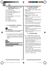
3.1 KNOWLEDGE OF THE
MACHINE (Fig. 21)
51) Guide handle
51a) Electric control box
52) Brush rotation start levers (on-off)
53) Water supply adjustment lever
54) Handle tilt lever
55) Power cable
56) Brush rotation lever release button
57) Machine body
58) Wheels
59) Supports
60) Electrical connection
61) Auxiliary socket (if any)
4.1 ADJUSTING HANDLE
TILT
(Fig. 22)
WARNING:
The handle position must be adjusted
while the appliance is at a standstill.
- By pulling the lever (63), it is possible
to vary the position of the handle (62).
When the lever is released, the handle is
positioned and locked in the closest fixed
position.
N.B.:
The correct position of the handle (62) during
machine operation is at hip height.
Never start the machine without having tilted
the handle correctly.
5.1 GUIDE HANDLE
(Figs. 21 and 23)
1) Brush rotation lever release button
(56) (Fig. 21)
Press the button (56) to release the brush
rotation start levers (52).
2) Brush rotation start levers (52)
(Fig. 21)
Pulling the brush rotation levers (52) ena-
bles brush rotation.
When the levers (52) are released, brush
rotation stops and the machine comes to
a halt automatically.
The levers (52) should be kept pulled to
achieve continuous machine operation.
3) Water supply adjustment lever (53)
(in the presence of an optional tank)
(Fig. 23)
Pulling the lever (64) activates the water
supply for washing the floor.
When the lever is released (64) the water
supply is interrupted.
6.1 OPERATION
6.1.a - Checks before use (Fig. 18)
- If the suction unit (optional) is assem-
bled, check that the suction tubes (48)
are properly connected to the base of the
machine and the aspirator.
- Check that the fittings on the base of the
machine are not blocked.
- If the tank (optional) is assembled, check
that it contains enough washing liquid for
the working phase and that the tubes are
properly connected.
- Check the condition of the brush or pad.
If worn, replace them.
- Check that the appliance, particularly the
mains cable, is not damaged in any way
that might compromise correct machine
operation or operator safety.
Manuale HU30-923_HOLLU_EM143 EM143 DS_1ed_07-2019.indd 6
16/07/2019 08:10:52
Summary of Contents for EM 143
Page 4: ...4 Copertina HU30 923_HOLLU_EM143 EM143 DS_1ed_07 2019 indd 4 15 07 2019 17 08 04 ...
Page 5: ...5 Copertina HU30 923_HOLLU_EM143 EM143 DS_1ed_07 2019 indd 5 15 07 2019 17 08 04 ...
Page 6: ...6 Copertina HU30 923_HOLLU_EM143 EM143 DS_1ed_07 2019 indd 6 15 07 2019 17 08 04 ...
Page 7: ...7 Copertina HU30 923_HOLLU_EM143 EM143 DS_1ed_07 2019 indd 7 15 07 2019 17 08 04 ...
Page 8: ...8 Copertina HU30 923_HOLLU_EM143 EM143 DS_1ed_07 2019 indd 8 15 07 2019 17 08 04 ...
Page 10: ...10 Copertina HU30 923_HOLLU_EM143 EM143 DS_1ed_07 2019 indd 10 15 07 2019 17 08 05 ...
Page 12: ...Copertina HU30 923_HOLLU_EM143 EM143 DS_1ed_07 2019 indd 12 15 07 2019 17 08 05 ...
Page 24: ...DEUTSCH 12 Manuale HU30 923_HOLLU_EM143 EM143 DS_1ed_07 2019 indd 12 16 07 2019 08 10 18 ...
Page 36: ...ENGLISH 12 Manuale HU30 923_HOLLU_EM143 EM143 DS_1ed_07 2019 indd 12 16 07 2019 08 11 10 ...
Page 48: ...ITALIANO 12 Manuale HU30 923_HOLLU_EM143 EM143 DS_1ed_07 2019 indd 12 16 07 2019 08 12 21 ...
Page 49: ...Copertina HU30 923_HOLLU_EM143 EM143 DS_1ed_07 2019 indd 13 15 07 2019 17 08 05 ...
Page 50: ...Copertina HU30 923_HOLLU_EM143 EM143 DS_1ed_07 2019 indd 14 15 07 2019 17 08 05 ...
Page 51: ...Copertina HU30 923_HOLLU_EM143 EM143 DS_1ed_07 2019 indd 15 15 07 2019 17 08 05 ...

