
7
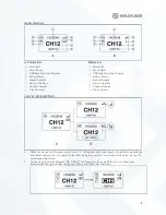
3.
The black and bold te xt on white background means that it is the DFS channel, wh ile the white te xt on
the black background is the non-DFS channel.
4.
When the device detects the USB d isk connected, the USB d isk detection display lights up.
5.
When the voltage is too low, the low battery alarm will be triggered and the icon will flash slowly .
Caution
1.
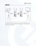
When the receiver is not connected, it will not display the hotpot number.
2.
When the receiver is turned on, the channel number will not be displayed bef
ore the receiver is
connected with transmitter.
CHANNEL CHANGE
Press the channel button “UP/DOW N” on the transmitter or rece iver to change the current channel.
Press “OK” to confirm the channel, then the channel of the transmitter and receiver will be
automaticallyandsynchronously changed.
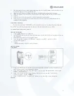
DEVICE UPGRADE
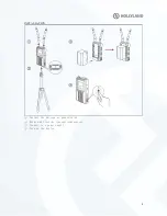
1.
Co
py upgrade fir
mwa re to a USB stick.
2.
Insert the USB stick into the OTG converter andconnect
it
with the USB Type-C upgrade interface on
the transmitter.
3.
Reset the device, and enter into upgrade interface.
4.
Once the upgrade is complete, it will display “upgrade successfully”, and device will be
automatically upgraded.
Caution
USB disk should be at FAT32 or e xFAT format.
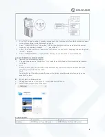
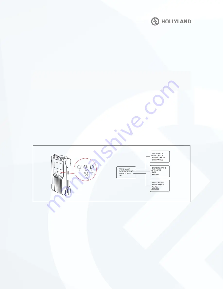
QUICK GUIDE
Transmitter
1.
Long press “OK” button for about 3 seconds, enteringintothe root menu interface, it includes scene
mode, system setting, version information options.
2.
Select “SCENE M ODE”, then clic k “OK” button, you can select “IMAGE MODE”, “ BALA NCE
MODE” , “SPEED MODE”.
3.
Select “SYSYTEM SETTING”,then clic king “OK” button, you can select “LANGUA GE
(Ch inese/English)”, “PAIR”
, “RESET”.
4.
Select “ VERSION INFO”, thenclic k “OK” button, you can check the version informat ion.
Recei ver


