14
15
Symptom
Possible Cause
Suggestion
LED Lights are Red
9V battery is flat.
Replace 9V Battery.
Single zone not working
Faulty solenoid coil, or break
in field wire.
Check fault indicator in
display.
Check solenoid coil (a good
solenoid coil should read around
33Ω on a multi meter). Test field
cable for continuity. Test common
cable for continuity.
No automatic start
Programming error or blown
fuse or transformer.
If unit works manually then
check the programming. If not
then check the fuse, wiring and
transformer.
Buttons not responding
Short on button or
programming not correct.
Unit may be in sleep
mode and no AC power.
Ensure programming is correct.
If buttons still not responding
then return panel to supplier or
manufacturer.
More than one zone
coming on at once
Possible faulty driver triac.
Check wiring and swap faulty
valve wires on the controller
terminal block with known
working zones. If the same
outputs are still locked on, return
panel to supplier or manufacturer.
Pump start chattering
Faulty relay or pump
contactor.
Electrician to check voltage on
relay or contactor.
Sensor input not working
Sensor enable switch in the
OFF position or faulty wiring.
Slide switch on front panel to
the ON position, test all wiring
and make sure the sensor is a
normally closed type. Check
programming to make sure
sensor is enabled.
Pump not working on a
specific zone or program
Programming error with
pump enable routine.
Check programming using the
manual as a reference and
correct mistakes.
Fault Finding Guide
Pump Protection (System Test)
In some circumstances not all operational zones
might be hooked up. For example, if the controller
was capable of running 8 zones but there were
only 6 field wires and solenoid valves available for
connection. This situation can pose a risk to a pump
when the system test routine for the controller is
initiated.
The system test routine sequences through all
available zones on the controller. In the above
example this would mean zones 6 through to 8
would become active and would cause the pump to
operate against a closed head. This could possibly
cause permanent pump, pipe and pressure vessel
damage.
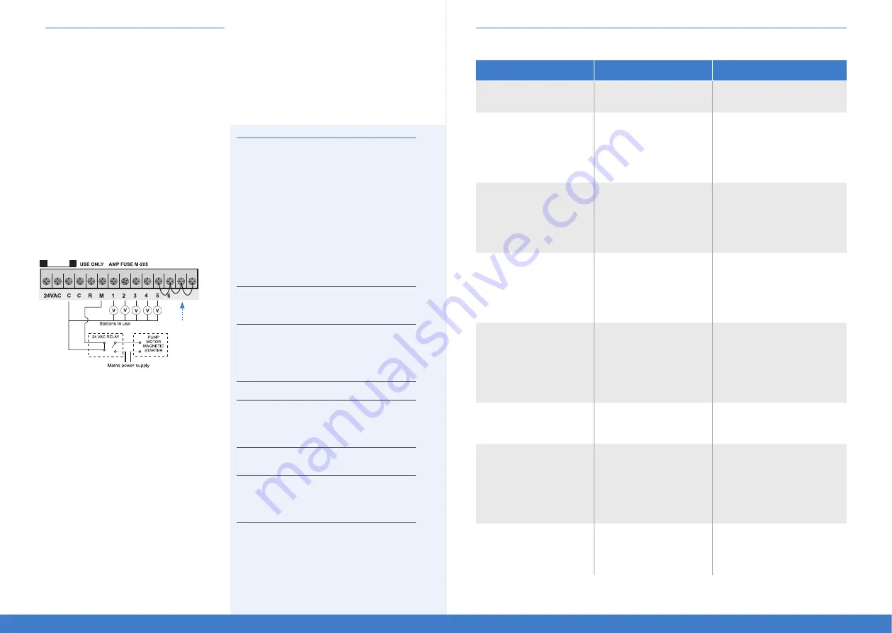
It is mandatory if the system test routine is going
to be used, that all unused, spare zones should be
linked together and then looped to the last working
zone with a valve on it.
Using the above example, the connector block
should be wired as per the diagram below.
Electrical Power Supply: Input 24V AC 50/60 Hz
Electrical Outputs: Maximum of 1.0 A
To solenoid valves:
24V AC 50/60 Hz 0.75 A max
Up to 2 valves per zone on the inbuilt model.
To the master valve/pump start:
24V AC 0.25 A max
Transformer and fuse capacity must be compatible
with output requirements.
Overload Protection: Standard 20mm M-205 1.0 A fast blow
glass fuse, protects against power surges.
Power Failure
The BTX8 does not have a permanent memory.
If AC and the 9V battery are not connected all
programmed settings will be lost. The 9V Alkaline
battery maintains the display during power outs,
and can be used for remote programming where
no AC power is available.
Note: The batteries do not run the outputs. The internal
transformer requires mains power to run the valves.
Servicing the Controller
The controller should always be serviced by an
authorised agent.
Follow these simple steps to return the unit:
1. Turn the mains power OFF to the controller.
a) If the controller is hardwired, a qualified
electrician will be required to remove the entire
unit depending on the fault.
b) Proceed to either unplug and return the entire
controller with transformer or disconnect the
panel assembly only for servicing or repair.
2. Disconnect the 24V AC leads at the controller
24V AC terminals on the very left hand side of
the terminal block.
3. Clearly mark or identify all valve wires according
to the terminals they are connected to, (1-8).
This allows you to easily wire them back to
the controller, maintaining your valve watering
scheme.
4. Disconnect valve wires from the terminal block.
5a) Remove the complete panel from the controller
housing by unscrewing the two screws in the
lower corners of the fascia (both ends of the
terminal block).
b) Remove the complete controller from the wall
unplugging the lead.
6. Carefully wrap the panel or controller in
protective wrapping and pack in a suitable
box and return to your service agent or the
manufacturer.
7. Replace your controller panel by reversing this
procedure.
Note: Tampering with the unit will void the warranty.
1
7
8
Link any unused
zones to the
last active valve.


