


16
Field Wiring Connections
PREPARATION
1.
Prepare wires for hook-up by cutting the wires to the correct length
and stripping approximately 6mm (¼ inch) of insulation from the end
to be connected to the controller.
2.
Ensure terminal block screws are loosened sufficiently to permit
easy access for wire ends. Insert stripped wire ends into the
clamp aperture and tighten screws.
Do not over tighten
as this
may damage the terminal block.
3.
A maximum of 0.5 Amps may be supplied by any output. Check
the inrush current of your solenoid coils before connecting more
than two valves to any one station.
Installation Instructions
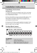
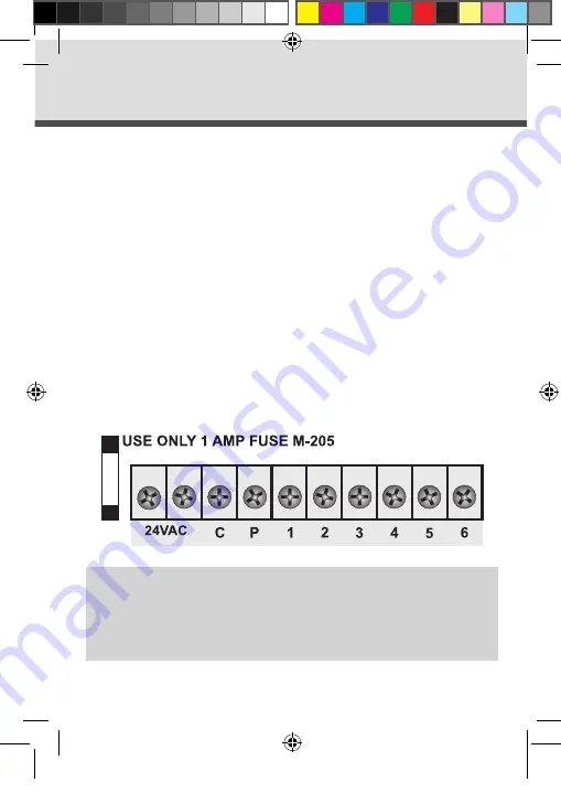
Terminal Block Layout
The terminal block is laid out as follows:
GLOSSARY
24VAC
24VAC Power Supply
C
Common valve wire input
P
Master valve or pump start active wire
ST1 to ST6
Station (Valve) active wire connection
DialEZY Controller 4 & 6 Station Instruction Manual Rev03.indd 16
10/06/2016 11:28 AM


