background image

MAINTENANCE PROCEDURES

A.  REPLACING HEATER TUBES


1) 

DISCONNECT UNIT FROM POWER SOURCE.


2)  Remove the enclosure, by removing screws.  Lift back end of enclosure up then back.


3)  Remove heater tube wires from terminal block connection, keeping top and  


  bottom wires separate.


4)  Lift heater tube retainers by loosening retaining screws and sliding the retainer plate up.   


  Hand tighten the plate to hold it up so the heater tubes will slide out freely.


5)  Gently, pull defective heater tube out of unit.


6)  Gently, put new heater tube into unit.


7)  Loosen retainer screws and slide the retainer back into place. Tighten the screw to  


  secure the retainer in place over the ends of the heater tubes.


8)  Reinstall the wires being sure use the same location as was in the original heater tube.   


  Tighten the screws securely.

B.  REPLACING FAN MOTOR 


1) 

DISCONNECT UNIT FROM POWER SOURCE

.


2)  Remove the enclosure, by removing screws.  Lift back end of enclosure up then back.


3)  Unplug power supply cord from fan motor.


4)  Remove (4) screws, which hold fan motor and grill to bottom of unit and remove fan.


5)  Put replacement motor and grill in place and secure to the bottom of unit with screws.


6)  Reconnect power supply cord to fan motor.


7)  Replace back panel and enclosure. Fasten with screws removed in step 2.

C.  REPLACING CONVEYOR DRIVE MOTOR 


1) 

DISCONNECT UNIT FROM POWER SOURCE.


2)  Remove enclosure and back panel.


3)  Remove sprocket from motor shaft, using an Allen wrench and loosening the set-screw.


4)  Remove the wire from terminal block connecting the drive motor to internal wiring.  


  On units rated 208 or 240 volts, note which color leads are being used for these connections  


  and which lead is capped with white tape. The new motor should use the same arrangement. 


5)  Remove screws holding motor in place and remove motor from unit.


6)  Put new motor in place and attach loosely with mounting screws.


7)  Replace sprocket on motor shaft.

NOTE:  The two sprockets must line up parallel with each other, so the chain does not twist any 

during operation.  Also the hub gets installed closets to the motor.


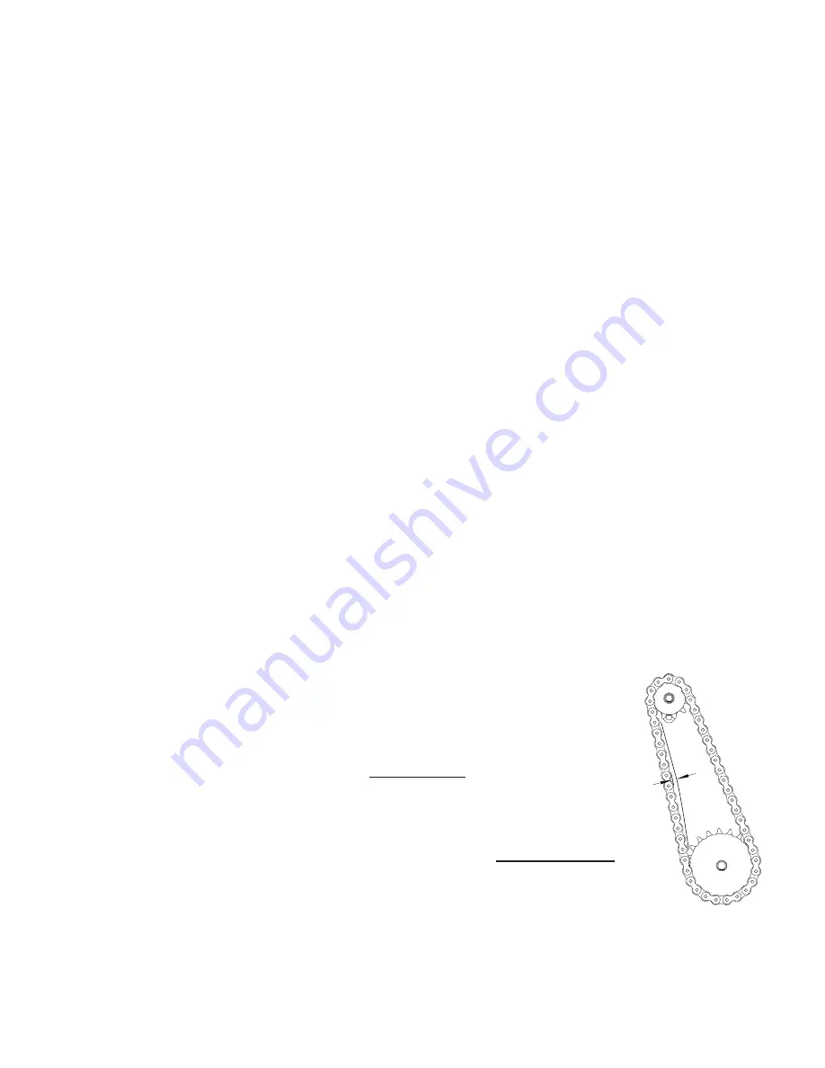
8)  Slide motor until the drive chain has about 1/4” slack when  


  lightly pushed at the center of its top open run.   


See chain tensioning illustration

.


9)  Tighten screws to secure motor.


10) Rewire leads same as removed in step 4.


11) Replace side panel and control box cover.

D.  CLEANING AIR INTAKE 

ONCE A WEEK


1) 

DISCONNECT UNIT FROM POWER SOURCE.


2)  Place unit on its backside.


3)  Use a vacuum cleaner and or a  damp cloth to clean 


  the air intake.  This procedure should be done at least 

E.  LUBRICATE THE CHAIN & SPROCKETS 

EVERY 6 MONTHS


1) 

DISCONNECT UNIT FROM POWER SOURCE.


2)  Remove enclosure exposing chain drive.


3)   Using an extreme pressure, synthetic chain lubricant with a 


  temperature range up to 400°F.  Apply liberally onto chain  


  and sprockets.  This grease is available as part no. 1P-Z8914.


4)  Replace enclosure, Reconnect power source and test unit.

1/4”

QCS/RCS Chain Tension

Summary of Contents for QCS-2-1200B

Page 1: ...CONVEYOR TOASTER MODEL QCS 2 1200B RCS 2 1200B QCS 3 1600B Installation and Operation Instructions 2M HG0656 Rev I 2 11 2011 QCS 2...

Page 2: ...ions in information provided or conclusions reached as a result of using the specifications By using the information provided the user assumes all risks in connection with such use MAINTENANCE AND REP...

Page 3: ...nd those from inside the cooking chamber If damage is discovered file a claim immediately with the carrier that handled the shipment Do not operate the unit if it was damaged during shipping ASSEMBLY...

Page 4: ...ectricity and keep the toaster warm When needed turn the switch to FULL POWER Recovery time is a few minutes CAUTION CERTAIN SURFACES ARE EXTREMELY HOT DURING OPERATION AND CARE SHOULD BE TAKEN WHILE...

Page 5: ...LEANING Preventive maintenance for your Holman toaster consists of the following recommended cleaning procedures To keep your toaster in its top operating condition these steps should be performed on...

Page 6: ...re and back panel 3 Remove sprocket from motor shaft using an Allen wrench and loosening the set screw 4 Remove the wire from terminal block connecting the drive motor to internal wiring On units rate...

Page 7: ...sk at 1 800 807 9054 as the drive motor and or speed control may need replacing 8 Replace the enclosure by sliding it forward towards the front of the unit The front edge of the enclosure will slide b...

Page 8: ...c utensils or abrasive cleaners This warranty does not apply to the non stick properties of such materials This warranty does not apply to Special Products but to regular catalog items only Star s war...

Page 9: ...D ORG BLK BRN BRN NOTE DRIVE MOTOR FOR 240V USE BLACK AND BLUE WIRES FOR 208V USE BLACK WHITE WIRES BRN BRN BRN BLK RED BLK BLK BLK BRN BRN MAJ MODEL QCS 2 1200B QCS3 95HNH QCS 3 1600B THIS DRAWING CO...

Page 10: ...G BLU NOTE DRIVE MOTOR FOR 240V USE BLACK AND BLUE WIRES FOR 208V USE BLACK WHITE WIRES WIRE DIAGRAM 208 220 240 VOLT SIRED SERIES 065021 01 31 05 WIRING DIAGRAM RCS 2 1200B SERPENTINE THIS DRAWING CO...

Page 11: ...0 21 23 24 25 26 30 31 32 33 34 35 36 37 39 38 22 29 40 41 17 MODEL QCS RCS 2 1200B 1600B CONVEYOR TOASTER THIS DRAWING CONTAINS INFORMATION CONFIDENTIAL TO STAR MFG INT L INC NO REPRODUCTION OR DISCL...

Page 12: ...202904 1 SHAFT IDLER 21 SP 160027 1 BELT CONVEYOR 10 X 35 1 2 2B 200601 1 LINK CONVEYOR BELT 23 HA 100560 1 TRAY PULL OUT 24 HC 402457 1 CRUMB TRAY 25 2R 200787 1 CRUMB TRAY GUARD Crumb Tray Mounting...

Page 13: ...SP 160028 1 BELT CONVEYOR 14 X 35 1 2 2B 200602 1 LINK CONVEYOR BELT 14 22 2B 200603 3 LINK MASTER CONVEYOR BELT 23 HA 100561 1 TRAY PULL OUT QCS3 24 HH 402465 1 CRUMB TRAY QCS 3 25 2R 200788 1 CRUMB...

Page 14: ...00700 2 BEARING FRONT TEFLON 20 2A 202904 1 SHAFT IDLER 21 SP 160027 1 BELT CONVEYOR 10 x 35 1 2 2B 200601 1 LINK CONVEYOR BELT 23 HA 100560 1 TRAY PULL OUT 24 HC 402457 1 CRUMB TRAY 25 2R 200787 1 CR...

Page 15: ...209114 2 37 HEATER TUBE METAL BOTTOM 208V 2N 209198 2 38 HEATER TUBE METAL TOP 220V 2N 209113 2 37 HEATER TUBE METAL BOTTOM 220V 2N 209192 2 38 HEATER TUBE METAL TOP 240V 2N 209112 2 37 HEATER TUBE ME...

Reviews: