Rev. 1.10
12
November 26, 2019
Rev. 1.10
13
November 26, 2019
HT68FB240
USB Low Speed Flash MCU
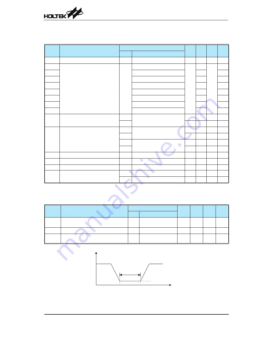
LVD & LVR Electrical Characteristics
Ta= 25°C
Symbol Parameter
Test Conditions
Min. Typ. Max. Unit
V
DD
Conditions
V
LVR1
Low Voltage Reset Voltage
—
LVR Enable
-5%
2.1
+5%
V
V
LVD1
Low Voltage Detector Voltage
—
LVDEN = 1, V
LVD
= 2.0V
-5%
2.0
+5%
V
V
LVD2
LVDEN = 1, V
LVD
= 2.2V
2.2
V
V
LVD3
LVDEN = 1, V
LVD
= 2.4V
2.4
V
V
LVD4
LVDEN = 1, V
LVD
= 2.7V
2.7
V
V
LVD5
LVDEN = 1, V
LVD
= 3.0V
3.0
V
V
LVD6
LVDEN = 1, V
LVD
= 3.3V
3.3
V
V
LVD7
LVDEN = 1, V
LVD
= 3.6V
3.6
V
V
LVD8
LVDEN = 1, V
LVD
= 4.0V
4.0
V
I
LVR
Additional Power Consumption if
LVR is used
3V
LVR disable → LVR enable
—
30
45
μA
5V
—
60
90
μA
I
LVD
Additional Power Consumption if
LVD is used
3V
LVD disable → LVD enable
(LVR disable)
—
40
60
μA
5V
—
75
115
μA
3V
LVD disable → LVD enable
(LVR enable)
—
30
45
μA
5V
—
60
90
μA
t
LVR
Low Voltage Width to Reset
—
—
120
240
480
μs
t
LVD
Low Voltage Width to Interrupt
—
—
20
45
90
μs
t
SRESET
Software Reset Width to Reset
—
—
45
90
120
μs
t
LVDS
LVDO stable time
—
For LVR enable, LVD off
→
on
—
—
15
μs
—
For LVR disable, LVD off
→
on
—
—
15
μs
Power on Reset Characteristics
Ta= 25°C
Symbol
Parameter
Test Conditions
Min.
Typ.
Max.
Unit
V
DD
Conditions
V
POR
V
DD
Start Voltage to Ensure Power-on
Reset
—
—
—
—
100
mV
RR
VDD
V
DD
Rise Rate to Ensure Power-on Reset
—
—
0.035
—
—
V/ms
t
POR
Minimum Time for V
DD
Stays at V
POR
to
Ensure Power-on Reset
—
—
1
—
—
ms


