Holtkamp Electronics VENUS 6600XL techn. Stand 04.2016 4074_04.2016 V09.2019
- 8 -
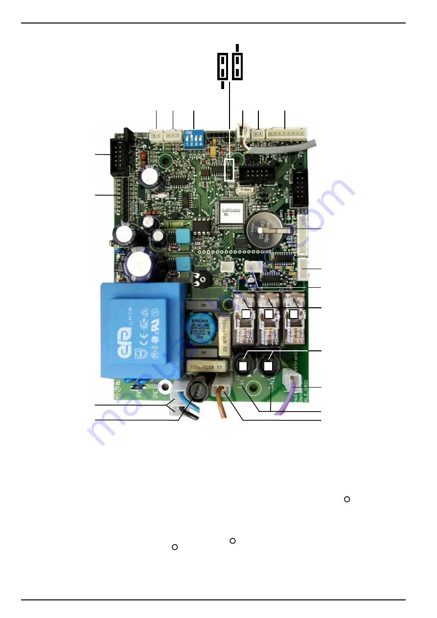
7.2 Illustration of electronic
1
Serial interface
2 Battery
3
Connection for serial remote display
4
Connection for bridge switch
5a
Additional relay for 110%-disconnection
5b
Main relay
5c
Lead relay
6a
Fuse main relay
6b
Fuse lead relay
7
Power connection
8
Connection for potential free relay
9
PCB fuse
10
Connection for foil keyboard
11
Connection for chip card contact unit
12
Connection for chip card reject
13
Connection for external timer
14
DIP switch no. 1-4
15
Connection for remote start
16
Connection for time hold/cleaning button
Special equipment
PCB XL2_V021 230V~
Jp FS = 0
Jp FS =
standard
Jumper remote start (FS):
without function
a
b
c
a
b
12 13
14
15 16
1
2
3
4
5 a, b ,c
6 a, b
7
8
7
7
9
10
11
Summary of Contents for VENUS 6600 XL
Page 1: ...Operating instruction VENUS 6600 XL Chip card system ...
Page 28: ...Holtkamp Electronics VENUS 6600XL techn Stand 04 2016 4074_04 2016 V09 2019 28 ...
Page 30: ...Holtkamp Electronics VENUS 6600XL techn Stand 04 2016 4074_04 2016 V09 2019 30 ...
Page 31: ...Holtkamp Electronics VENUS 6600XL techn Stand 04 2016 4074_04 2016 V09 2019 31 ...


