ASSEMBLY
HOLZMANN MASCHINEN GmbH www.holzmann-maschinen.at
54
ED1080ADIG
N O T I C E
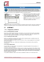
When mounting a chuck or face plate, first make sure that the cam-lock studs are
properly fixed. Otherwise, the chuck/face plate may never be removed again later
because the cam-lock studs have become twisted.
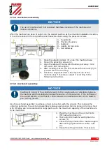
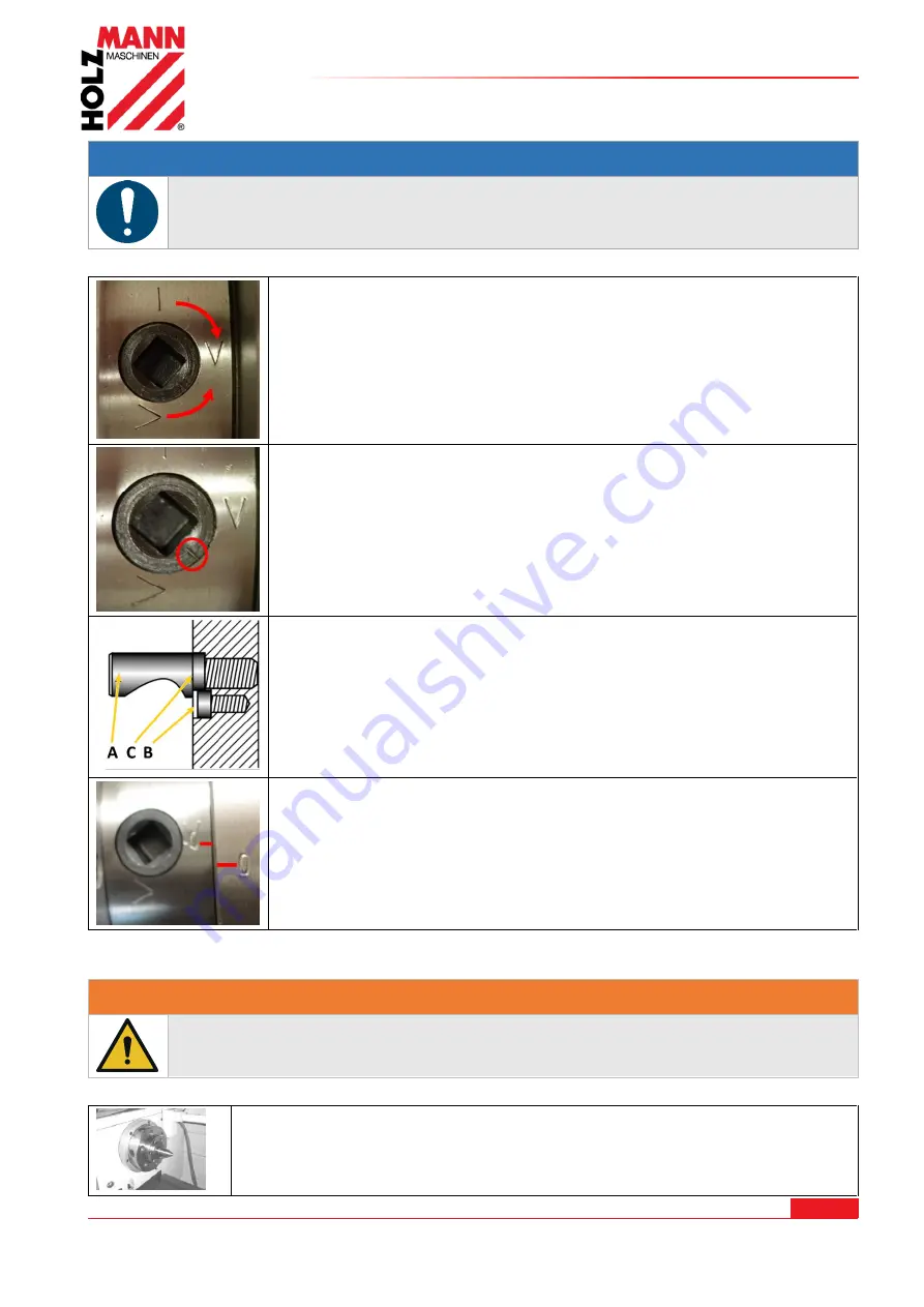
Carefully disassemble the jaw chuck. To do this, loosen the cam-locks by
turning them clockwise (approx. one third of a turn) using the clamping
key supplied and carefully remove the jaw chuck.
Check the cam-lock studs. Ensure that they are not damaged or broken
during transport. Clean all parts thoroughly. Also clean the spindle and
the cam-locks. Lightly oil the spindle, cam-locks, camlock studs and
chuck body with a suitable machine oil.
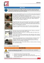
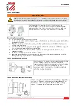
Then lift the jaw chuck up to the spindle nose and press on the spindle.
Tighten the cam-lock studs by turning the cam-locks counterclockwise.
After tightening, the cam-lock line should be located between the two V-
marks - see illustration on the left.
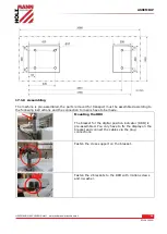
If a cam is not within this mark, remove the chuck or face plate and
adjust the height of the cam-lock studs - see the following illustration.
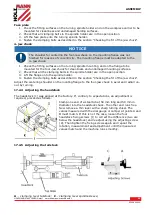
The cam-lock stud is correctly adjusted when the mark (C) carved into
the stud is flush with the back of the chuck.
If the cam-lock line is outside the V markings, adjust the height of the
relevant cam-lock stud.
To do this, first loosen the retaining screw (B), adjust the cam-lock stud
by turning it in/out one full turn at a time and then tighten the retaining
screw firmly again.
If the chuck (clamping device) is correctly fastened, a reference mark
should be attached to the spindle and clamping device so that the
clamping device can always be released and remounted in the same
position to ensure optimum concentricity.
Do not change chucks or face plates between machines without checking
for correct cam-locking.
17.2.3
Mounting workpiece holders
W A R N I N G
The max. spindlespeed of the machine must be lower than the max. permissible
speed of the used workpiece holder.
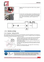
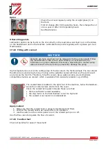
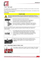
Centring tip
1.
Clean the inner taper of the spindle holder.
2.
Clean the morse taper and the taper of the centering tip.
3.
Press the centring tip with the morse taper into the inner taper of the
turning spindle holder.
Summary of Contents for ED1080ADIG
Page 84: ...ERSATZTEILE SPARE PARTS HOLZMANN MASCHINEN GmbH www holzmann maschinen at 84 ED1080ADIG 2...
Page 85: ...ERSATZTEILE SPARE PARTS HOLZMANN MASCHINEN GmbH www holzmann maschinen at 85 ED1080ADIG...
Page 86: ...ERSATZTEILE SPARE PARTS HOLZMANN MASCHINEN GmbH www holzmann maschinen at 86 ED1080ADIG...
Page 87: ...ERSATZTEILE SPARE PARTS HOLZMANN MASCHINEN GmbH www holzmann maschinen at 87 ED1080ADIG...
Page 88: ...ERSATZTEILE SPARE PARTS HOLZMANN MASCHINEN GmbH www holzmann maschinen at 88 ED1080ADIG 6...
Page 93: ...ERSATZTEILE SPARE PARTS HOLZMANN MASCHINEN GmbH www holzmann maschinen at 93 ED1080ADIG 2...
Page 94: ...ERSATZTEILE SPARE PARTS HOLZMANN MASCHINEN GmbH www holzmann maschinen at 94 ED1080ADIG 3...

