11
HBS Series | Version 1.06
Settings
8
Settings
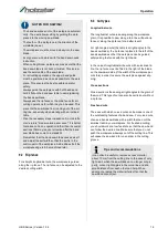
8.1 Setting of the 90° table square
The table may be set at 90o to the saw blade by adju
-
sting the table stop screw under the table. The table stop
screw rests on the top of the lower wheel bandwheel
housing (Fig. 8):
Fig. 8: 90°-Stellung des Sägetisches
Step 1: First loosen the clamping nut (Fig. 8, Pos. A).
Step 2: Adjust the screw (Fig. 8, Pos. B) as follows, that
the angle between table and band saw blade is
90°. (Check this with an angle if necessary).
Step 3: Retighten the clamping nut (Fig. 8, Pos. A), ma
-
king sure that the setting is maintained.
8.2 Tilting the table
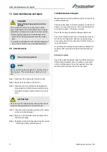
The saw table inclination can be set as follows:
Step 1: Loosen the lock handle (Fig. 9, Pos. A) on the ta
-
ble trunnion.
Step 2: Turn the table tilting knob (Fig. 9, Pos. B) to ad
-
just the table to the desired angle. Use the angle
indicator scale on the trunnion bracket to find the
desired angle..
Step 3: Retighten the lock handle to secure the table.
Fig. 9: Slope adjustment of the saw table
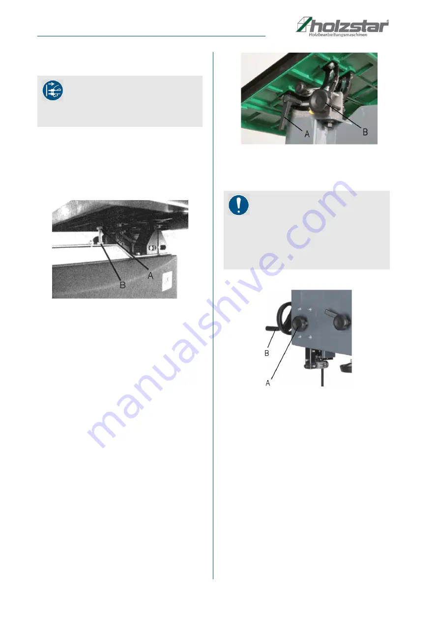
8.3 Adjusting the saw blade guide
Fig. 10: Adjusting the saw blade guideg
Step 1: Loosen the clamping screw (Fig. 10, Pos. A).
Step 2: Adjust the optimum height by turning the hand
-
wheel (Fig. 10, Pos. B).
Step 3: Clamp the saw band guide using the clamping
screw (Fig. 10, Pos. A).
ATTENTION!
The machine must be switched off and the mains
plug disconnected before all adjustment, set-up and
maintenance work is carried out on the machine.
NOTE!
The upper saw band guide must be adjusted accor
-
ding to the height of the workpiece. The upper band
guide unit should be set approximately 2-3 mm higher
than the thickness of the workpiece to be sawn. The
adjustment must be carried out or checked before
each sawing operation.


