background image

Spare parts

HBS Series | Version 1.06

22

Spare parts drawing 3 - HBS 400 

Fig. 20: Spare parts drawing 3 - Wood Band Saw HBS 400

Summary of Contents for 5900410

Page 1: ...HBS 400 Operating Instructions HBS S ERIES Wood Band Saw HBS 400 HBS 471 HBS 473 ...

Page 2: ... saw 5 2 6 Safety devices 5 3 Intended Use 6 4 Technical Data 6 4 1 Table 6 4 2 Type plate 6 5 Transport packaging and storage 7 5 1 Delivery 7 5 2 Transport 7 5 3 Packaging 7 5 4 Storage 7 6 Description of device 7 6 1 Machine 7 6 2 Scope of delivery 8 6 3 Accessories 8 7 Setting up and connection 8 7 1 Requirements for the place of operation 8 7 2 Set up the wood band saw 8 7 3 Electrical connec...

Page 3: ...hinen de We are always interested in valuable experience and knowledge gained from using the application whichthen could be shared and be valuable to develop ourproducts even further 1 3 Disclaimer All data in these operating instructions has been com piled on the basis of the state of the art valid standards and guidelines as well as our many years of expertise and experience The manufacturer sha...

Page 4: ...ed protec tive equipment shall be mandatory Operators shall also be responsible for maintaining the machine in a technically perfect condition For this rea son the following shall apply Operators shall make sure that the maintenance in tervals described in these operating instructions are complied with Operators shall regularly check that the safety equipment is fully functional and complete 2 3 O...

Page 5: ...s identifications are attached to the band saw Fig 1 and must be observed Fig 1 Safety labels 1 Safety instructions read operating instructions wear eye pro tection wear ear protection wear respiratory protection wear protective clothing wear safety shoes no smoking 2 warning signs Warning of danger of retraction on drive rollers warning of cuts warning of danger points warning of dangerous electr...

Page 6: ...rkpieces 3 Break tear of the tool 4 Fire hazard due to insufficient ventilation of the motor 5 Hearing impairment during prolonged work without hea ring protection 6 Contact with rotating parts or tools 7 Contact with live parts 4 Technical Data 4 1 Table 4 2 Type plate Fig 2 Type plate HBS 473 ATTENTION Certain types of wood and wood products produce harmful dust emissions when processed Therefor...

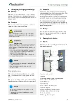
Page 7: ...band saw thoroughly cleaned in a dry clean and frost free environment Cover the machine with a protective plane 6 Description of device 6 1 Machine Illustrations in these operating instructions may de viate from the original Fig 3 Wood Band Saw HBS 473 1 Mount 2 Saw band tension display Display window 3 Hand wheel Saw band tension 4 ON OFF switch 5 Parallel stop 6 Hand wheel Saw band speed 7 Saw b...

Page 8: ...ion or work area must be dry and well venti lated 7 2 Set up the wood band saw The wood band saw is already delivered largely as sembled Only a few parts like the saw table the rip fence and the handwheels have to be assembled after delivery Step 1 After unpacking park the machine at the desired location Step 2 Screw the base plate of the machine to the sub strate via the holes using four M10 scre...

Page 9: ...the rear fence rail and then into the front fence rail Fig 6 Assembly of the rip fence Assembly of the handwheels Step 1 Mount the small handle Fig 7 Pos 1 in the lo wer position Step 2 Mount the large handle Fig 7 Pos 2 to the up per position Fig 7 Assembly of the handwheels Use a 14 mm or 10 mm open end wrench to fasten it 7 3 Electrical connection When connecting the power supply make sure that...

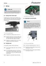
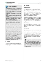
Page 10: ...lting knob Fig 9 Pos B to ad just the table to the desired angle Use the angle indicator scale on the trunnion bracket to find the desired angle Step 3 Retighten the lock handle to secure the table Fig 9 Slope adjustment of the saw table 8 3 Adjusting the saw blade guide Fig 10 Adjusting the saw blade guideg Step 1 Loosen the clamping screw Fig 10 Pos A Step 2 Adjust the optimum height by turning ...

Page 11: ...tep 1 By turning the handwheel Fig 12 Pos A the saw blade tension is increased or decreased by means of a spring Step 2 The correct tension can be read off the scale Fig 12 Pos B Fig 12 Saw blade tension Use protective gloves NOTE Make sure that the teeth of the saw band face the front edge of the table and the tips of the teeth point downwards NOTE If the band saw is not used for a longer period ...

Page 12: ...ed as listed below Upper saw blade guide Fig 14 Saw blade guide Step 1 First loosen the screw and push the rollers up to approx 1 5 mm towards the saw blade teeth Step 2 Clamp the screw again Step 3 To adjust the lateral guide rollers Fig 14 Pos D loosen the clamping plates Fig 14 C and adjust the guide rollers with the adjusting screw Fig 14 Pos B so that there is a gap of approx 0 5 0 7 mm betwe...

Page 13: ...tep 2 Move the scale along the mark in the window If necessary you can also insert the screw Fig 16 A in another position to fix the scale Step 3 To check the settings saw a test piece first if necessary and readjust the scale 8 9 Changing the saw band speed The wood band saw has a high and a low saw band speed On the lower impeller Fig 17 A and two belt pulleys of different sizes are mounted on t...

Page 14: ...can make uncontrolled movements and lead to serious injuries Disconnect the mains plug before making any adju stments to the machine WARNING Risk of injury There is a risk of injury to the operator and other per sons if they do not comply with the following rules The Wood Band Saw may only be operated by an instructed person The operator must not work when under the influ ence of alcohol drugs or ...

Page 15: ...e automati cally The user allows cutting by guiding the work piece into the moving saw blade The teeth cut the workpiece in the direction of the worktable down The workpiece must be moved slowly into the saw blade Every person who works with the band saw needs instruction When cutting thicker workpieces make sure that the band saw blade is not bent or twisted This increa ses the service life of th...

Page 16: ...t tension after the first 20 hours of operation After every 250 operating hours every six months check the V belt for wear po rosity and tension All protective and safety devices must be reinstalled im mediately after completion of repair and maintenance work Extraction system Check the extraction system daily for sufficient function If the extraction system does not function or functions only to ...

Page 17: ...damaged 4 The saw band guides are not adju sted correctly 1 Use the rip fence 2 Press the saw band with the workpiece 3 Insert a new saw band 4 Readjust the saw band guide The saw band does not cut or cuts only very slowly 1 The saw band teeth are blunt due to the sawing of wrong material 2 The saw band was installed the wrong way round 1 Insert the correct saw band for the mate rial to be process...

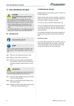
Page 18: ...ion 1 2 Customer service The following key data is required for queries or spare parts orders Device type Item number Position number Year of construction Quantity Desired shipping type post freight sea air ex press Shipping address Spare parts orders without the aforementioned data can not be taken into account The supplier shall determine the shipping type if no relevant data was provided Data o...

Page 19: ...00 The following spare parts drawings are intended to help identify the necessary spare parts To order please send a copy of the list of spare parts with the marked components to your dealer Spare parts drawing 1 HBS 400 Fig 18 Spare parts drawing 1 Wood Band Saw HBS 400 ...

Page 20: ...21 HBS Series Version 1 06 Spare parts Spare parts drawing 2 HBS 400 Fig 19 Spare parts drawing 2 Wood Band Saw HBS 400 ...

Page 21: ...Spare parts HBS Series Version 1 06 22 Spare parts drawing 3 HBS 400 Fig 20 Spare parts drawing 3 Wood Band Saw HBS 400 ...

Page 22: ...he following spare parts drawings are intended to help identify the necessary spare parts To order please send a copy of the list of spare parts with the marked components to your dealer Spare parts drawing 1 HBS 471 HBS 473 Fig 21 Spare parts drawing 1 Wood Band Saw HBS 471 HBS 473 ...

Page 23: ...Spare parts HBS Series Version 1 06 24 Spare parts drawing 2 HBS 471 HBS 473 Fig 22 Spare parts drawing 2 Wood Band Saw HBS 471 HBS 473 ...

Page 24: ...25 HBS Series Version 1 06 Spare parts Spare parts drawing 3 HBS 471 HBS 473 Fig 23 Spare parts drawing 3 Wood Band Saw HBS 471 HBS 473 ...

Page 25: ...ams HBS 400 Fig 24 Electrical circuit diagram HBS 400 HBS 471 Fig 25 Electrical circuit diagram HBS 471 HBS 473 Fig 26 Electrical circuit diagram HBS 473 Main switch Protective switch Main switch Power supply Protective switch 1 phase motor Protective switch Main switch 3 phase motor ...

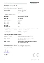
Page 26: ...plicable directives subse quently added including the changes applicable at the time the declaration was made Relevant EU directives 2014 30 EU EMC Directive The following harmonized standards have been applied DIN EN ISO 12100 1 2010 Safety of machinery General principles for design Risk assessment and risk reduction DIN EN 60204 1 2014 Safety of machinery Electrical equipment of machines Part 1 ...

Page 27: ...EU Declaration of Conformity HBS Series Version 1 06 28 Notes ...

Page 28: ...www holzstar de ...

Reviews: