background image

6

ADH-Series | Version 1.02

Safety

2.5 Safety labels on the Planer-Thicknesser 

The following safety labels and instructions are attached 
to the Planer-Thicknesser s (Fig. 1) and must be             
observed.


Fig. 1: Safety labels

1 Warning of danger | 2 Warning of dangerous electrical 
voltage | 3 Warning of hand injuries | 4 Warning of danger of 
entanglement I 5 Ground symbol | 6 Mandatory signs 

If safety labels on the machine are damaged or missing, 
this can cause errors, personal injury and material      
damage. The safety symbols attached to the machine 
must not be removed. Damaged safety symbols must 
be replaced immediately.

As soon as the signs are not clearly visible and compre-
hensible at first glance, the machine must be stopped 
until new signs have been attached. 

2.6 For your own safety 

The European standards must be observed when instal-
ling, operating, maintaining and repairing the planer-
thicknesser. For the European standards not yet trans-
posed into the respective national law, the still valid 
country-specific regulations must be applied. 

Operators of planer-thicknesser outside the scope of 
the European Standards are obliged to comply with the 
safety and accident prevention regulations applicable in 
the country of operation. If necessary, appropriate mea-
sures must be taken to comply with the country-specific 
regulations before the planer-thicknesser is put into 
operation.

Safety during operation

Before using the planer-thicknesser, make sure that the 
following is true

- there is no danger to persons.
- no things are damaged.
-  do not work in any way that could compromise 

safety.

-  use personal protective equipment such as a dust 

mask, ear protection, protective goggles.

- The residual hazards listed below basically exist on 

planer-thicknessers and cannot be completely 
averted by safety devices.

2

3

1

4

5

6

WARNING!

-  A planer-thicknesser is a dangerous machine that 

can cause serious injury if left unattended. It is the-
refore essential that you follow the following safety 
instructions:

-  The planer-thicknesser may only be put into opera-

tion and operated by persons who are familiar with 
the planer-thicknesser and are aware of the dan-
gers involved in working with the planer.

-  Persons under 18 years of age may only use the 

planer-thicknesser within the scope of a vocational 
training and under the supervision of a trainer.

WARNING!

Always disconnect the planer-thicknesser from the 
electrical power supply when carrying out adjust-
ment, inspection, cleaning or maintenance work.

DANGER!

Do not use your fingers to look for end position swit-
ches in order to be able to switch on the planer-thic-
knesser in a way other than intended.

Summary of Contents for 5904026

Page 1: ...ADH 26 C Operating Instructions ADH 26 C 230V 400V ADH S ERIES Planer Thicknesser ADH 31 C 230V 400V ADH 41 C 400V ADH 31 C ...

Page 2: ...Planer Thicknesser 6 2 6 For your own safety 6 2 7 Safety equipment 7 2 8 General safety instructions 8 3 Indended Use 9 4 Technical Data 9 4 1 Operating conditions 9 4 2 Type plate 9 4 3 Table 10 5 Transport packaging storage 11 5 1 Delivery and transport 11 5 2 Packaging 11 5 3 Storage 12 6 Description of device 12 7 Setting up and connection 12 7 1 Requirements for the place of operation 12 7 2...

Page 3: ...e submit any information and experiences you make during application of the machine as these may be valuable for product improvements 1 3 Disclaimer All data in this operation manual has been compiled on the basis of the state of the art valid standards and gui delines as well as our many years of expertise and ex perience The manufacturer shall not be liable for damage in the following cases Fail...

Page 4: ...vide staff with the required pro tective equipment and wearing the required pro tective equipment shall be mandatory Operators shall also be responsible for maintaining the machine in a technically perfect condition For this rea son the following shall apply Operators shall make sure that the maintenance intervals described in these operating instructions are complied with Operators shall regularl...

Page 5: ...Personal protective equipment Personal protective equipment is intended to protect the health and safety of persons at work Staff must wear the personal protective equipment indicated in individual sections of these operating instructions when carrying out the different tasks on the machine The personal protective equipment is described in the following section Head protection The industrial helme...

Page 6: ... operation If necessary appropriate mea sures must be taken to comply with the country specific regulations before the planer thicknesser is put into operation Safety during operation Before using the planer thicknesser make sure that the following is true there is no danger to persons no things are damaged do not work in any way that could compromise safety use personal protective equipment such ...

Page 7: ...he specified po wer range Use the planer only for the purpose for which it is intended Before each switch on make sure that there are no objects such as tools in the planer thicknesser 2 7 Safety equipment Undervoltage release In the event of an electrical power failure an undervol tage relay is triggered This prevents the planer thick nesser from starting up again on its own as soon as electrical...

Page 8: ...the machine Switch off the machine before carrying out main tenance work on the machine and disconnect the plugs from the machine Do not modify the machine in a way that poses a risk to safe operation Carry out regular inspections in accordance with the instructions for use Check and ensure that the machine is not subject to any malfunctions caused by the user After the work is finished adjust the...

Page 9: ... material assets can be endangered the function of the dressing plane may be impaired Stürmer Maschinen GmbH assumes no liability for con structive and technical changes to the planer thicknes ser Claims of any kind for damage due to improper use are excluded 4 Technical Data 4 1 Operating conditions The machine is not intended for outdoor use The machine is not intended for operation under explo ...

Page 10: ...ght product mm 960 1010 1010 Net weight kg 170 210 260 Input power drive motor kW 2 3 2 2 2 84 2 77 3 73 Output power drive motor kW 1 7 2 2 3 Electrical connection V 230 400 230 400 400 Phase s Ph 1 3 1 3 3 Rated frequency Hz 50 50 50 Length planing table mm 1120 1295 1640 Width planing table mm 275 325 425 Working height mm 830 850 850 Max depth of planing mm 3 3 3 Length thicknessing table mm 5...

Page 11: ...be slow and without jolting or swinging Put down the machine with the crane on the selected place Unpacking Step 1 Remove all parts from the carton Do not throw away the carton or packaging material until the machine is set up and running satisfactorily Step 2 Inspect the contents for transport damage Re port any damage to your dealer Tools required for assembly 1x Cross point Screwdriver approx 2...

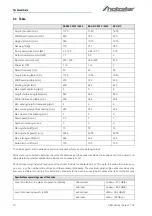
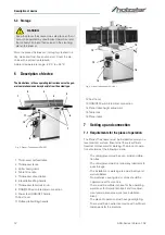
Page 12: ...ock 16 Planer table 7 Setting up and connection 7 1 Requirements for the place of operation The Planer Thicknesser must be installed securely on a level and firm surface Ensure that there is sufficient freedom of movement for working The place of opera tion should meet the following criteria The underground must be even solid and vibra tion free The underground must not allow any lubricants to pas...

Page 13: ... the direction in dicated on the plate If the direction of rotation is incor rect the connections of the phase lines must be re placed 8 Operation CAUTION Risk of injury from an improperly installed machine Check the stability of the machine after setting it up on stable ground CAUTION Observe the weight of the machine The machine may only be set up by two persons together Check the correct dimens...

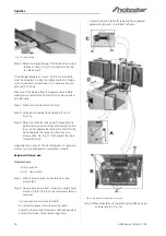
Page 14: ...th the ma chine 8 1 1 Conversion from planer to thickness function Fig 5 Operating elements Step 1 Release both housing locks Pos A Fig 5 by rotating the handles toward the operator then pulling away from the machine Step 2 Raise the table Pos C Fig 5 using the handle Pos B Fig 5 Table is heavy Use care when raising Failure to comply may cause serious injury When raised the table should be in the ...

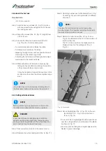
Page 15: ...of the planer Power feed Placing the planer power feed handle Pos D Fig 8 in the up position turns the planer power feed on see ar row Placing the handle in the down position turns the power feed off Table lock Turn the table lock Pos E Fig 8 clockwise to lock the height adjustment handwheel Pos F Fig 8 and secure the planer table Pos C Fig 8 in its selected position Turn the table lock Pos E Fig ...

Page 16: ... Fig 9 Step 2 Raise the lifting handle E to raise the infeed ta ble for a shallow depth of cut Lower the handle for a deeper cut Step 3 Tighten the lock knob Pos D Fig 9 Fig 9 Thicknesser Cutter head guard Properly positioned the cutter head guard Pos H Fig 10 should rest against the fence Pos A Fig 10 Fence movement The fence Pos A Fig 10 can be moved forward Pos B Fig 10 or backward Pos C Fig 10...

Page 17: ...be coplanar For optimum performance of the jointer the infeed and outfeed tables must be coplanar If they are not the fi nished workpiece may have a slight taper or twist across jointed its width or length The tables have been set coplanar at the factory but they should be double checked by the operator Also as the machine undergoes use the tables should be checked occasionally and adjusted if nec...

Page 18: ...that adjusts the table pitch and tilt at the back towards the fence and two hex cap screws Pos A1 Fig 13 that adjusts the table toward the front Adjustment can consist of a front adjustment rear adju stment or more probable a combination of both Adjustment of the rear area Required tools 13 mm wrench 4 mm hex wrench Step 1 With a 13mm wrench loosen three hex cap screws B1 Step 2 Using a 4mm hex wr...

Page 19: ...d Pos B Fig 11 Step 3 Carefully number each knife blade Pos C Fig 14 and Fig 15 with a magic marker to differen tiate each Step 4 Rotate the cutter head Pos E Fig 14 and Fig 15 and determine the 12 o clock position of knife number one The 12 o clock position is the highest point a blade will reach in the cutting arc Pos C Fig 15 Fig 14 Cutter head Step 5 Set a straightedge Pos J Fig 14 on the out ...

Page 20: ...p 2 Remove the cutter head guard Pos B Fig 9 Step 3 Turn all five screws Pos A Fig 14 and Fig 15 into the lock bar Pos B Fig 14 and Fig 15 by turning in a clockwise direction as viewed from the infeed table Pos G Fig 14 and Fig 15 Step 4 Carefully remove the cutter knife Pos C Fig 14 and Fig 15 and lock bar Pos B Fig 14 and Fig 15 Step 5 Repeat for remaining two knives Step 6 Thoroughly clean all ...

Page 21: ...wrench is helpful but not necessary Step 3 Remove two button head socket screws Pos C Fig 16 and upper back panel Pos D Fig 16 Step 4 Remove four button head socket screws Pos O Fig 16 and lower back panel Pos P Fig 16 Cutter head drive belt replacement Step 5 Loosen four motor mount screws Pos L Fig 16 Lift the motor and rest it in the horizontal slot side of the motor mount opening This will cre...

Page 22: ... Adjustment of the planer table Checking planer table parallel to cutter head The planer table is set parallel to the cutter head at the factory and no further adjustment should be needed If your machine is planing a taper first check to see if the knives are properly adjusted in the cutter head see Setting cutter head knives and make adjustments if necessary After the knives are confirmed to be p...

Page 23: ...o the cutter head tighten the hex cap screws Pos H Fig 18 8 3 Initial start up Do not put the machine into operation until you have familiarised yourself with the contents of the operating instructions instructions for use Make sure that the electrical cables are not dama ged to avoid injury from electric current Check regularly that the safety covers are cor rectly fitted and not damaged Repair d...

Page 24: ...rmly against the infeed table and fence while the right hand pushes the workpiece in a smooth even motion toward the cutter head Step 2 After the cut is under way the new surface rests firmly on the outfeed table The left hand is transferred to the outfeed side Figure 19 and presses down on this part of the workpiece at the same time maintaining flat contact with the fence The right hand presses t...

Page 25: ...The planer against the grainmay result in chipped and splintered edges Feed with the grain to obtain a smooth surface as shown in Figure 22 Fig 22 Operation in grain direction 8 6 Thicknessing Thicknessing or edging is the process of creating a fi nished flat edge surface that is suitable for joinery or fi nishing Figure 23 It is also a necessary step prior to ripping stock to width on a table saw...

Page 26: ... fence Keep fingers near top of push block Several passes may be required to achieve the full be vel will probably take several passes 8 8 Planer operations Depth of cut Thickness planing refers to the sizing of lumber to a de sired thickness while creating a level surface parallel to the opposite side of the board Board thickness that the planer will produce is indicated by the scale and the dept...

Page 27: ... kickback and reduce snipe Equipment of the work process The planer thicknesser is supplied with planer blades mounted in the cutter head and infeed and outfeed rol lers adjusted to the correct height The planer feed is automatic it will vary slightly depending on the type of wood Preparation Feed rate refers to the rate at which the lumber travels through the planer The operator is responsible fo...

Page 28: ...the instructions is sued by the machine manufacturer Only use original spare parts to replace parts or tools Use only specified types or lubricating oils and greases or those that comply with them If a belt in the belt kit is longer than specified re place the entire kit completely Do not use compressed air to clean the machine or remove chips 9 1 Blade care The condition of the blades will affect...

Page 29: ...sion of the drive belt Loose bolts and nuts Worn or damaged switches Worn or damaged planing knives Step 8 Check the drive belt every 3 months monthly if used daily replace if worn or damaged 9 3 1 Functional testing A functional test should be carried out before each use Step 1 The drive belt must be tensioned Step 2 The planing knife must rotate freely and must not jam Step 3 Check the connectin...

Page 30: ...ives knife inserts The workpiece feed is too fast Use a slower feeding speed Cutting to deepty Make shallower cuts Knots imperfections in wood Inspect wood closely for imperfections use diffe rent stock if necessary Structure is fibrous The wood has a high moisture content Allow the wood to dry or use a drying chamber Blunt knives Sharpen or replace the knives knife inserts The cutter head slows d...

Page 31: ...umber not butted pro perly Butt end to end each piece of stock at the pass through Structure is fibrous The wood has a high moisture content Allow the wood to dry or use a drying chamber Blunt knives Sharpen or replace the knives knife inserts Torn grain Too heavy a cut Adjust proper depth of cut The knives cut against the grain Cut in grain direction Blunt knives Sharpen or replace the knives Rou...

Page 32: ...cut scale Depth of cut scale uncor rect Adjust depth of cut scale Problem Possible cause Solution Problem Possible cause Solution Chain jumping Inadequate tension Adjust the chain tension Sprockets misaligned Align sprockets Sprockets are worn Replace the sprockets Machine does not start does not restart No incoming power Check that the device is connected to the power supply the START button is p...

Page 33: ...working you have two options Have the motor starter tested for function by a qua lified electrician or buy a new starter and determine whether the problem was when it was replaced Switch or motor failure how to distinguish If you have access to a voltmeter you can distinguish a starter fault from a motor failure by first checking the input voltage at 220 20 V and the voltage between the starter an...

Page 34: ...nformation for requests or orders of spare parts Type of device Item No Position No Year of construction Quantity Required mode of dispatch mail freight sea air express Address of dispatch Spare part orders which do not include the above indi cations may not be taken into consideration If the indi cations regarding the mode of dispatch are missing the product is dispatched at the discretion of the...

Page 35: ...er ADH 26 C The following drawings are intended to identify the required spare parts in the event of service If applicable submit a copy of the parts drawing including the highlighted components to your authorised retailer Spare parts drawing 1 Fig 26 Spare parts drawing 1 ADH 26 C ...

Page 36: ...36 ADH Series Version 1 02 Spare parts Spare parts drawing 2 Fig 27 Spare parts drawing 2 ADH 26 C ...

Page 37: ...Spare parts ADH Series Version 1 02 37 Spare parts drawing 3 Fig 28 Spare parts drawing 3 ADH 26 C ...

Page 38: ...38 ADH Series Version 1 02 Spare parts Spare parts drawing 4 Fig 29 Spare parts drawing 4 ADH 26 C ...

Page 39: ...Spare parts ADH Series Version 1 02 39 Spare parts drawing 5 Fig 30 Spare parts drawing 5 ADH 26 C ...

Page 40: ...40 ADH Series Version 1 02 Spare parts Spare parts drawing 6 Fig 31 Spare parts drawing 6 ADH 26 C ...

Page 41: ...Spare parts ADH Series Version 1 02 41 Spare parts drawing 7 Fig 32 Spare parts drawing 7 ADH 26 C ...

Page 42: ...er ADH 31 C The following drawings are intended to identify the required spare parts in the event of service If applicable submit a copy of the parts drawing including the highlighted components to your authorised retailer Spare parts drawing 1 Fig 33 Spare parts drawing 1 ADH 31 C ...

Page 43: ...Spare parts ADH Series Version 1 02 43 Spare parts drawing 2 Fig 34 Spare parts drawing 2 ADH 31 C ...

Page 44: ...44 ADH Series Version 1 02 Spare parts Spare parts drawing 3 Fig 35 Spare parts drawing 3 ADH 31 C ...

Page 45: ...Spare parts ADH Series Version 1 02 45 Spare parts drawing 4 Fig 36 Spare parts drawing 4 ADH 31 C ...

Page 46: ...46 ADH Series Version 1 02 Spare parts Spare parts drawing 5 Fig 37 Spare parts drawing 5 ADH 31 C ...

Page 47: ...Spare parts ADH Series Version 1 02 47 Spare parts drawing 6 Fig 38 Spare parts drawing 6 ADH 31 C ...

Page 48: ...er ADH 41 C The following drawings are intended to identify the required spare parts in the event of service If applicable submit a copy of the parts drawing including the highlighted components to your authorised retailer Spare parts drawing 1 Fig 39 Spare parts drawing 1 ADH 41 C ...

Page 49: ...Spare parts ADH Series Version 1 02 49 Spare parts drawing 2 Fig 40 Spare parts drawing 2 ADH 41 C ...

Page 50: ...50 ADH Series Version 1 02 Spare parts Spare parts drawing 3 Fig 41 Spare parts drawing 3 ADH 41 C ...

Page 51: ...Spare parts ADH Series Version 1 02 51 Spare parts drawing 4 Fig 42 Spare parts drawing 4 ADH 41 C ...

Page 52: ...52 ADH Series Version 1 02 Spare parts Spare parts drawing 5 Fig 43 Spare parts drawing 5 ADH 41 C ...

Page 53: ...Spare parts ADH Series Version 1 02 53 Spare parts drawing 6 Fig 44 Spare parts drawing 6 ADH 41 C ...

Page 54: ...54 ADH Series Version 1 02 Spare parts Spare parts drawing 7 Fig 45 Spare parts drawing 7 ADH 41 C ...

Page 55: ...Version 1 02 55 13 Electrical circuit diagrams Models ADH 26 C 230 V and ADH 31 C 230 V Fig 46 Electrical circuit diagram ADH 26 C and ADH 31 C Models ADH 26 C 400 V ADH 31 C 400 V and ADH 41 C Fig 47 Electrical circuit diagram ADH 26 C and ADH 31 C 400 V Models and ADH 41 C Switch ...

Page 56: ...l as the version that we have put into circulation with the relevant fundamental health and safety requirements of subsequent EU Directives Relevant EU Directives 2014 30 EU EMC Directive The following harmonized standards have been applied EN 60204 1 2014 10 Safety of machines Basic concepts general principles for design Part 1 General requirements DIN EN ISO 12100 2010 Safety of machinery Genera...

Page 57: ...Notes ADH Series Version 1 02 57 15 Notes ...

Page 58: ...www holzstar de ...

Reviews: