


14
SAA Series | Version 1.06
Spare parts
11.4 Disposal by municipal collection point
The appliance contains electric and electronic compo
-
nents and may not be disposed as domestic waste. Ac
-
cording to European directive about old electric and
electronic appliances and the conversion into national
law, electric power tools and electric machines must be
collected apart and be supplied to an environmentally
sound recycling.
The symbol on the product or its packaging
points out that this product is not to be treated
as a normal domestic waste, but must be deli
-
vered to collecting company for the recycling
of electric and electronic devices. By your contribution to
correct disposal of this product you protect the environ
-
ment and the health of people. Environment and health
are endangered by wrong disposal. Recycling of material
helps the consumption to reduce of materials. You
receive further information about the recycling of this
product from your municipality, the municipal disposal
companies or from the trader, where you have bought
the product.
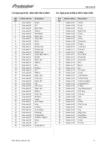
12 Spare parts
12.1
Spare parts orders
Spare parts are available from authorised retailers or di
-
rectly from the manufacturer. The contact details have
been listed in section 1.2 Customer service.
Always quote the following key data with your spare
parts orders:
- Device type
- Serial number
- Quantity
- Designation
- Desired shipping type (post, freight, sea, air, ex
-
press)
- Shipping address
Spare parts orders without the aforementioned data can
-
not be taken into account. The supplier shall determine
the shipping type if no relevant data was provided.
Example
You must order the fan base for the Chip Extraction Unit
SAA 2001. The Fan has the position number 22 in the
spare parts drawing.
Device type:
Chip Extraction Unit SAA 2001
Article number:
5922201
Position number:
22
Your order number is:
0-5922201-22
The order number is made up of the article number
5922201, the position number and one digit in front of
the article number.
- Add a leading 0 in front of the article number.
- Also add a 0 in front of the item numbers 1 to 9.
Item number of your machine:
Chip Extraction Unit SAA 2001
5922201
Chip Extraction Unit SAA 2003
5922203
Chip Extraction Unit SAA 3001
5922301
Chip Extraction Unit SAA 3003
5922303
DANGER!
Risk of injury caused by the use of
incorrect spare parts!
The use of incorrect or faulty spare parts may cause
risks for operating staff and damage as well as
malfunctions.
- Exclusively genuine spare parts made by the manu
-
facturer or spare parts authorised by the manufactu
-
rer shall be used.
- Always contact the manufacturer if you are unsure.
NOTE!
The manufacturer warranty shall be rendered void in
the event of a use of unauthorised spare parts.
Summary of Contents for 5922201
Page 20: ...www holzstar de ...


