


8
SAA Series | Version 1.06
Intended use
3
Intended use
The Chip Extraction Unit serves for the extraction of
chips and dust which are produced when wood or wood-
like materials are processed. The Extraction Unit is con
-
structed for the application in not explosion-threatened
surroundings and may be installed and operated in dry
rooms only. The observance of all information in these
instructions also belongs to the designated use. Every
different use except of the designated use is considered
as a false use.
The exhaust system has not been designed for commer
-
cial, craft or industrial use. We do not assume any war
-
ranty if the machine is used in commercial, handicraft or
industrial drives as well as in similar activities.
Claims of any kind for damages caused by improper use
are null and void.
4
Technical Data
4.1 Table
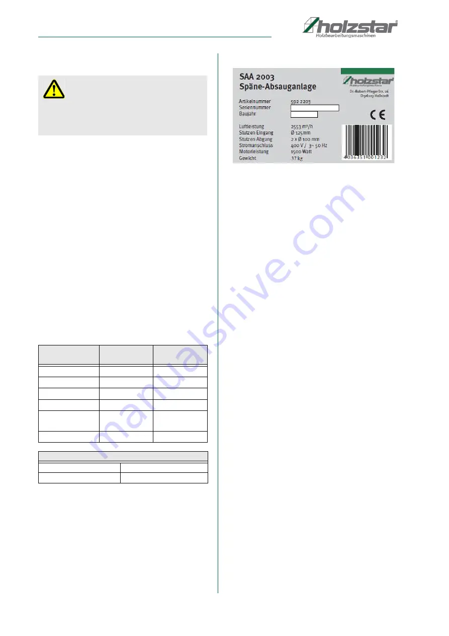
4.2 Type plate
Fig. 2: Type plate SAA 2003
5
Transport, packaging, storage
5.1 Delivery and transport
Check the Chip Extraction Unit for visible transport da
-
mage upon delivery. In case of visible damage to the
Chip Extraction Unit, immediately notify the carrier or
your retailer.
5.2 Packaging
All of the Chip Extraction Unit‘s packaging materials and
packing aids are suitable for recycling and must always
be disposed of using material-based recycling systems.
Packaging materials made of cardboard must be shred
-
ded and recycled as waste paper.
The foils are made of polyethylene (PE), padding is
made of polystyrene (PS). Dispose of these substances
at a recycling centre or hand them over to a qualified wa
-
ste disposal company.
5.3 Storage
Always store the Chip Extraction Unit in a clean condition
and a dry, clean and frost-free environment. It must not
be stored in the same room as chemicals.
Cover the machine with a protective tarpaulin.
WARNING!
On not designated use of the aspiration system there
will be generated dangers for the staff, the aspiration
system and other objects of the operator, furthermore
the function of the machine can be affected.
Model
SAA 2001/
SAA 2003
SAA 3001 /
SAA 3003
Air flow rate
2.553 m
³
/h
3.910 m
³
/h
Duct input
Ø
125 mm
Ø
150 mm
Duct output
2 x
Ø
100 mm
3 x
Ø
100 mm
Motor output
1,5 kW
2,2 kW
Dimensions
[L x W x H]
1.000 x 750 x
2.000 mm
1.450 x 800 x
2.000 mm
Weight
37 kg
48kg
Electrical connection:
SAA 2001/ SAA 3001
230 V/50 Hz
SAA 2003 / SAA 3003
400 V/50 Hz
Summary of Contents for 5922201
Page 20: ...www holzstar de ...


