background image

Care, maintenance and overhaul/repair

ADH-Series | Version 1.05

15

9 Care, maintenance and overhaul/re-

pair 

9.1 Care after working

Step 1: Remove the power plug from the socket. 

Step 2: Drain and clean the extraction device 

Step 3: Clean the machine of chips and planer dust with 

the compressed air (Important: Use the protec-
tive glasses and the breathing protection!)          
and/or with a dry cleaning cloth.

Step 4: Spray or lubricate all unpainted metal surfaces 

with some anti-rust spray.

Step 5: Lubricate the shaft and the bearing.

Step 6: Check the machine for damage on the safety 

devices and on the planer knife. If necessary, in 
compliance with the Safety, the repair execute.

Step 7: Check the machine regularly for:

- Right tension of the driving belt
- Loose screws and nuts
- The worn or damaged Switch
- The worn or damaged the planer knife.

Step 8: Check every 3 months, in case of daily use - 

every month the drive belt. Replace in case of 
wear or damage.

9.2 Maintenance and repair 

Maintenance and repair work may only be carried out by 
qualified personnel.

Should the Planer-Thicknesserdoes not work properly, 
contact your dealer or our customer service. Contact 
details can be found in chapter 1.2 Customer.

All protection and safety devices must be reinstalled af-
ter completion of repair and maintenance work 
immediately

9.2.1 Functional check 

The Planer-Thicknesser is delivered ready for use.

Before each use, a functional check should be carried 
out. 

Step1: The driving belt must be tension. 

Step 2: The planer knife must rotate free and must not 

clamp.

Step 3: Check the connecting cable for damage.

9.2.2 Extraction device

Check daily the extraction device on the sufficient func-
tion. If the extraction device does not work or is 
restricted, it must be restored. Only then can the Planer-
Thicknesser be put into operation.

9.2.3 Lubrication 

Lubricate regularly the bearing and guides. Oiling the 
shaft and threaded rod.

9.2.4 Change of the drive belt

The drive belt must not come into contact with oil or fat. 
It must be checked regularly at the wear, cracks and  
brittleness. If necessary, replace the drive belt, but at 
least once a year.

DANGER!

Electric shock is life-threatening!

There is a danger of life in case of contact with cur-
rent running through components.Electrical compo-
nents that are on can cause uncontrolled movements 
and lead to the most serious injuries.
-  Always disconnect the mains plug before you start 

cleaning and maintenance works.

-  Connections and repairs of the electrical equip-

ment may only be carried out by specialized elec-
trical staff.

Use protective gloves!

NOTE!

Never use strong detergents for all cleaning work. 
This can lead to damage or destruction of the device. 

Summary of Contents for ADH 200

Page 1: ...Instruction manual ADH S ERIES Planer Thicknesser ADH 200 ADH 250 ADH 305 ADH 250 ADH 200 ...

Page 2: ... of symbols 3 2 2 Operator responsibility 4 2 3 Operating staff qualification 4 2 4 Personal protective equipment 5 2 5 Safety labels on the Planer Thicknesser 5 2 6 Safety devices 5 2 7 General safety aspects 6 3 Designated use 7 4 Technical Data 8 4 1 Type plate 8 5 Transport packaging storage 8 5 1 Delivery and transport 8 6 Machine description 9 6 1 Illustration 9 6 2 Scope of supply 9 7 Insta...

Page 3: ...ase submit any information and experiences you make during application of the machine as these may be valuable for product improvements 1 3 Disclaimer All data in this operation manual has been compiled on the basis of the state of the art valid standards and guidelines as well as our many years of expertise and experience The manufacturer shall not be liable for damage in the following cases Fail...

Page 4: ...e required pro tective equipment shall be mandatory Operators shall also be responsible for maintaining the machine in a technically perfect condition For this rea son the following shall apply Operators shall make sure that the maintenance intervals described in these operating instructions are complied with Operators shall regularly check that the safety equipment is fully functional and complet...

Page 5: ...lowing safety labels and instructions are attached to the Planer Thicknesser s Fig 1 and must be observed Fig 1 Safety labels 1 Warning of dangers 2 Warning of dangerous electrical voltage 3 Warning of hand injuries 4 Warning of entanglement hazard 5 Use of gloves prohibited 6 Safety instructions If safety labels on the machine are damaged or missing this can cause errors personal injury and mater...

Page 6: ...arry tool by cable or rank it to disconnect it from socket Keep cable from heat oil and sharp edges 11 Do not abuse the cord Never yank the cord to disconnect it from the so cket Keep the cord away from heat oil and sharp edges 12 Secure work Where possible use clamps or a vice to hold the work It is safer than using your hand 13 Don t overreach Keep proper footing and balance at all times 14 Main...

Page 7: ...for the prevention of kickback and the feed spindle should be regularly inspected to ensure safe operation 30 Tools equipped with chip collection and extractor hoods shall be connected to the dust and chip coll ecting device 31 Use the tool only for wood or similar materials When the blade be abraded 95 you must change it to the new one which must meeting EN847 1 32 Need two persons for moving rou...

Page 8: ... 8500 rpm Number of planing knives 2 2 2 Extraction duct Ø 80 mm 80 mm 80 mm Dimensions LxWxH mm 1105x 550x570 1135x 600x570 Weight 29 kg 40 kg 42 kg Sound pressure level in the air LpA ca 98 dB A ca 98 dB A ca 98 dB A Sound power level LwA ca 107 dB A ca 107 dB A ca 107 dB A Sound pressure level at the work place LpA ca 89 dB A ca 89 dB A ca 89 dB A Planer Max planing width 204 mm 254 mm 305 mm P...

Page 9: ...lock cover 6 ON OFF switch 7 Tool kit 8 Outfeed table 9 Overload protection switch 10 Height setting of thicknesser Fig 4 Hobelmesserwelle A Screw B Clamping segment C Planer D Spring E Bearing 6 2 Scope of supply ADH 200 Planing machine Chip extraction hood Jointer fence Tube Dust bag Instruction manual ADH 250 305 Planing machine Chip extraction hood Jointer fence Push stick Screw Clamping screw...

Page 10: ...e sure the planer thicknesser doesn t rock and the tables are level Fig 5 Hole separation ADH 200 ADH 250 ADH 305 Mounting of the parts Step 1 Attach the aluminium fence on the Planer Thicknesser with the 6 1 0 x 16 mm screws Step 2 Assembly the Chip extraction hood with the two brackets depending on the operating mode and activate the safety switch Step 3 Connect the extraction hose and the dust ...

Page 11: ...st injuries Disconnect the mains plug before you start any works on the machine WARNING Danger to life There is danger to life for the operator and for other persons if they do not comply with the following rules Handling and working with the Planer Thicknesser is permitted only to persons who are familiar with the handling and the mode of operation of the machine The operator must not work if he ...

Page 12: ...9 on desired depth on the scale Pos O Fig 9 Step 4 Adjust the cover Pos P Fig 9 so that the kniffe shaft is covered Fig 8 Adjustment of the knife shaft cover Step 5 Power the machine on with the green ON switch Step 6 Press the workpiece with one hand against the Infeed table and angle fence After that move the workpiece with the other hand constant Fig 9 Adjustment of the material guide on the pl...

Page 13: ...le Remember The current workpiece height minus Desired chip removal is the end hight Step 7 Power the machine on with the green ON switch Step 8 Place the workpiece with the working area up wards Step 9 If the workpiece not moved by automatic workpiece feed pull the workpiece manual out Step10 After completion of the work cycle switch off the machine with the red STOP button Step 11 During a furth...

Page 14: ... 15 Adjustment of the cutter block on the surface B 8 4 Workflow Step1 Make adjustments to the machine for the thicknessing operation and connect the extrac tion device Step 2 Plug the power supply in the socket Step 3 Switch on the extraction device Step 4 Power the machine on with the green ON switch Step 5 Place the workpiece and execute the thicknes sing operation Step 6 After completion of th...

Page 15: ...stalled af ter completion of repair and maintenance work immediately 9 2 1 Functional check The Planer Thicknesser is delivered ready for use Before each use a functional check should be carried out Step1 The driving belt must be tension Step 2 The planer knife must rotate free and must not clamp Step 3 Check the connecting cable for damage 9 2 2 Extraction device Check daily the extraction device...

Page 16: ...ste management company For the recycling process please request the assist ance of a specialized waste disposal centre if required 11 3 Disposal of lubricants The manufacturer of the lubricant makes the disposal in structions for the used lubricants available If applica ble ask for the product specific data sheets Malfunction Possible cause Remedy Engine does not start Power supply is ON OFF Switc...

Page 17: ...e type arti cle number and year of manufacturing on the type plate which is fixed on the device Example It is necessary to order the driving belt for the Planer Thicknesser ADH 250 The driving belt has part number 167 on the spare parts drawing Type of machine Planer Thicknesser ADH 250 Article number 5905250 Position number 167 The order No is 0 5905250 17 The order No consists of the article num...

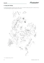
Page 18: ...s 13 2 Spare parts drawings The following drawings are intended to help in case of service to identify necessary spare parts To order send a copy of the parts drawing with marked components to your dealer Fig 17 Spare parts drawing ADH 200 ...

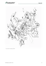
Page 19: ...Spare parts ADH Series Version 1 05 19 Fig 18 Spare parts drawing ADH 250 ...

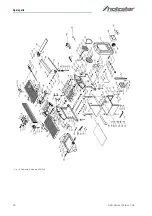
Page 20: ...20 ADH Series Version 1 05 Spare parts Fig 19 Spare parts drawing ADH 305 ...

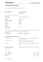
Page 21: ...put into circulation with the relevant fundamental health and safety requirements of subsequent EU Directives Relevant EU Directives 2014 35 EU Low Voltage Directive 2014 30 EU EMC Directive The following harmonized standards have been applied DIN EN 60204 1 2007 06 Safety of machines Basic concepts general principles for design Part 1 General requirements DIN EN ISO 12100 2010 Safety of machinery...

Page 22: ...www holzstar de ...

Reviews: