10
DH-Series | Version 1.01
Description of device
6
Description of device
The illustrations in these operating instructions serve the gen-
eral comprehension and may deviate from the actual type.
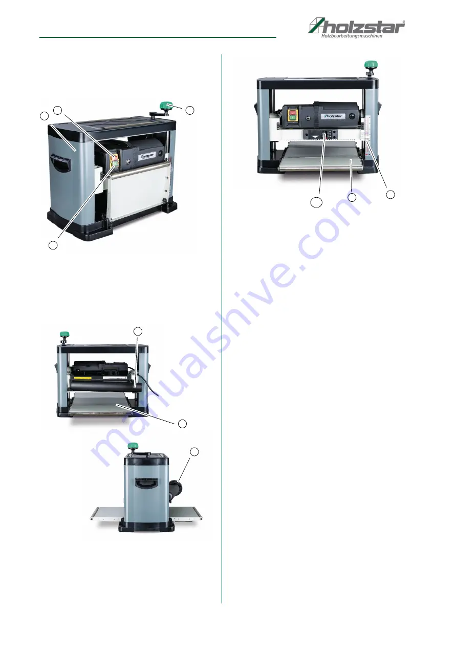
Fig. 3: Planer
1 Planer
2 STOP Button
3 START Button
4 Hand crank: height adjustment of the planer
Fig. 4: Planer
5 Dust chute
6 Outfeed table
7 Adapter of the dust chute
Fig. 5: Planer
8 Infeed table
9 Depth scale
10 Measuring instrument for the cutting depth
7
Setting up and connection
7.1 Requirements for the place of operation
The planer must be installed securely on a level and firm
surface. Ensure that there is sufficient freedom of move-
ment for working. The place of operation should meet
the following criteria:
- The underground must be even, solid and vibra-
tion-free.
- The underground must not allow any lubricants to
pass through.
- The installation or working area must be dry and
well ventilated.
- No machines causing dust or chips should be
operated near the machine.
- There must be sufficient space for the operating
personnel, for material transport and for adjust-
ment and maintenance work (see installation
plan).
- The place of operation must have good lighting.
- There must be an extraction device with sufficient
dimensions for the machine.
3
4
1
2
5
7
6
9
8
10


