12
DH-Series | Version 1.01
Setting up and connection
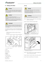
Fig. 9: Mounting of the hand crank
Step 6: Remove the polystyrene insert located between
the main table and the blade drum. Peel the pro-
tective film from the main table.
Fig. 10: Remove the transport insert
Step 7: Attach the dust chute to the machine using two
thumb screws.
Step 8: The dust chute can be mounted to direct chips
to either side of planer.
Fig. 11: Mounting of the dust chute
The planer features four holes in the base for mounting
to a workbench or worktable.
The planer should be mounted level bench or table be-
fore operation.
Fig. 12: Mounting holes
The machine must be anchored in the ground with
screws before operation.
Mounting the suction hose
Fig. 13: Suction connection
Step 1: Mount the suction hose to the adapter.
ATTENTION!
Only start up the machine when it is stable!
NOTE!
It is recommended that the planer be used with a
dust extraction system for a cleaner and safer wor-
king environment. Using a dust extraction system will
also help prevent clogging of the dust chute. An
adapter is provided for matching dust extraction
system better.
Polystyrol-
einsatz
Schutz-
film
Tips and recommendation
Die Absaugvorrichtung für Späne und Staub muss
eine ausreichende Leistung bei einer Strömungs-
Geschwindigkeit von min. 20 m/s gewährleisten.
Staubschacht
Staubschacht
Montagelöcher


