background image

Operation

KGZ 305 E | Version 1.09 | EN

9

8.1  Pre-adjustment

8.1.1 Setting the mitre angle (mitre cut)

In addition to the stepless adjustment of the mitre angle, 
there are fixed angle positions at 0°, 15°, 22.5°, 30° and 
45°.

The angle for the mitre cut is set on the angle scale of the 
saw table as follows:

Step 1: Loosen the table lock. To do this, turn the adju-

sting knob for the table arrest open (Fig. 8). 


Fig. 8: Setting the mitre angle

Step 2: Use the setting mark and the angle scale with 

markings to set the desired mitre angle in 1° 
steps. There are snap-in points for the angles 0°, 
15°, 22.5°, 30° and 45°.

Step 3: Lock the table in the set angle position by turning 

the knob.

8.1.2 Inclination of the saw head (inclined cut)

The saw head can be tilted up to 45° to the left and right 
(see Fig. 10). Snap-in points exist for 15° and 30° in both 
directions. Proceed as follows for the inclined position:


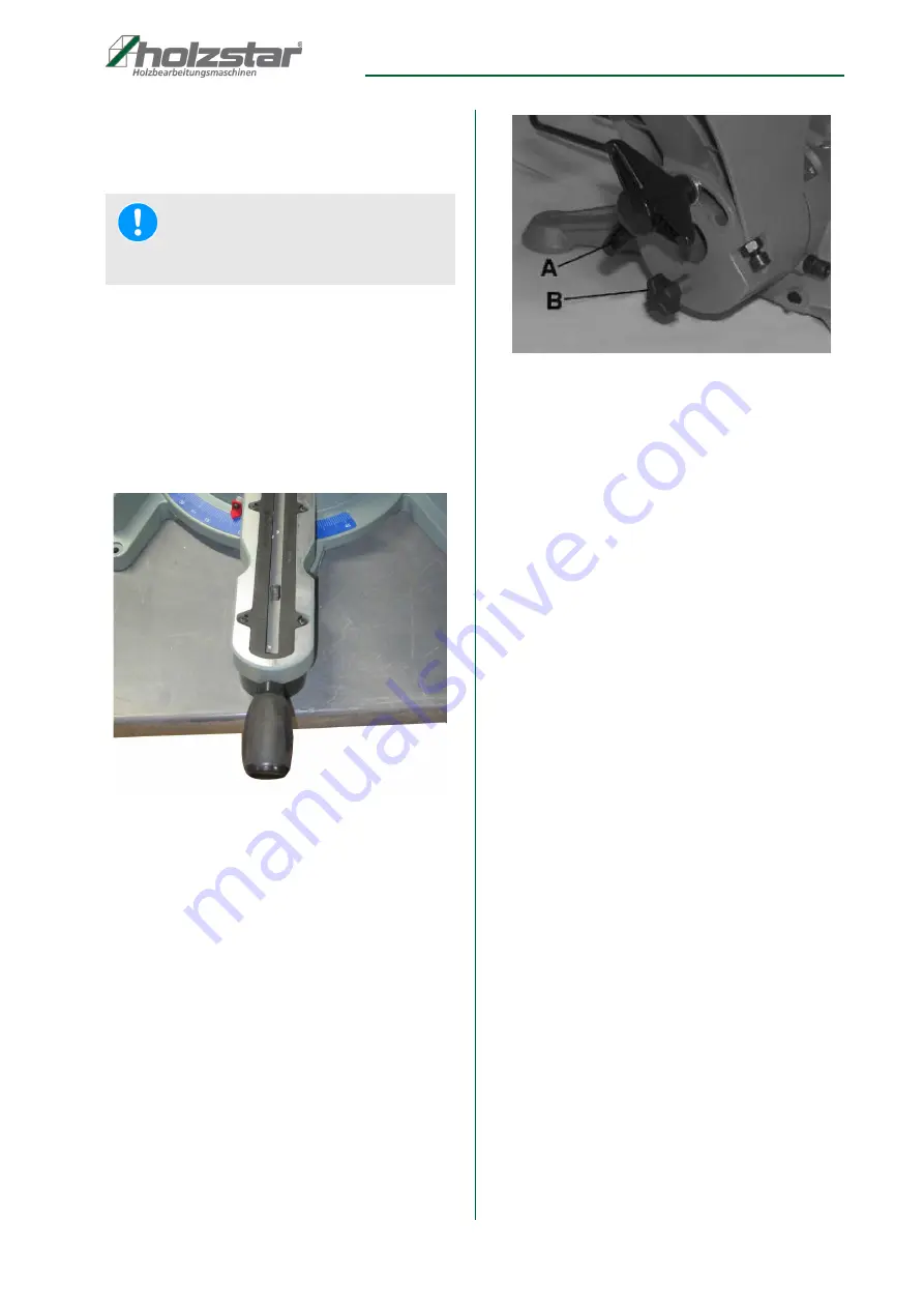
Fig. 9: Adjusting the angle of inclination

Inclined position - stepless

Step 1: Hold the saw head by the saw head retaining 

handle.

Step 2: Loosen the locking screw (A, Fig. 9) and pull the 

locking knob (B). 

Step 3: Tilt the saw head to the left or right by the desired 

angle. The angle scale assigned to the tilt posi-
tion with markings in 1° increments is located at 
the rear end of the table.

Step 4: Loosen the locking knob and tighten the locking 

screw.

Inclination - in 15° steps 

Step 1: Hold the saw head by the saw head retaining 

handle.

Step 2: Loosen the locking screw.

Step 3: Pull the locking knob in 15° increments to deacti-

vate locking.

Step 4: Tilt the saw head to the desired 15° step. The 

angle scale at the rear end of the table, which is 
assigned to the oblique position, is provided with 
markings for the 15° steps.

Step 5: Release the locking knob and move the saw 

head a few degrees until the locking knob au-
dibly engages in the 15° step.

Step 6: Tighten the locking screw.

Step 7: Tilt the locking knob and move the saw head a 

few degrees.

NOTE!

Select a mitre angle of 0° for a vertical cross-section 
(90° section)!

Summary of Contents for KGZ 305 E

Page 1: ...KGZ 305 E Operating Instructions KGZ 305 E KGZ 305 E Chop and Mitre Saw ...

Page 2: ...rror Contents Imprint 2 Contents 2 1 Introduction 3 1 1 Copyright 3 1 2 Customer service 3 1 3 Disclaimer 3 2 Safety 3 2 1 Legend of symbols 3 2 2 Personal protective equipment 4 2 3 Safety labels on the chop and mitre saw 4 3 Intended Use 5 4 Technical Data 5 4 1 Type plate KGZ 305 E 5 5 Transport packaging and storage 6 5 1 Delivery and transport 6 5 2 Packaging 6 5 3 Storage 6 6 Description of ...

Page 3: ...il ersatzteile stuermer maschinen de We are always interested in valuable experience and knowledge gained from using the application whichthen could be shared and be valuable to develop ourproducts even further 1 3 Disclaimer All data in these operating instructions has been com piled on the basis of the state of the art valid standards and guidelines as well as our many years of expertise and exp...

Page 4: ...TENTION This combination of symbol and signal term indicates a potentially hazardous situation which may cause minor or light injuries if it is not averted IMPORTANT This combination of symbol and signal term indi cates a potentially dangerous situation which may cause material damage or harm the environment if it is not averted NOTE This combination of symbol and signal term indicates a potential...

Page 5: ...e for both pri vate and commercial use Intended use also includes compliance with all the information in these instructions Any use that goes beyond the intended use or any other use is considered misuse For structural and technical changes to the chop and mitre saw the company Stürmer Maschinen GmbH assu mes no liability Claims of any kind due to damage due to improper use are excluded 4 Technica...

Page 6: ...for recycling and must always be dispo sed of using material based recycling systems Packaging materials made of cardboard must be shred ded and disposed of as part of waste paper recycling The foils are made of polyethylene PE padding is made of polystyrene PS Dispose of these substances at a recycling centre or hand them over to the relevant waste disposal company 5 3 Storage Store the chop and ...

Page 7: ...sition to the secured rest position Press the saw head lightly downwards to release the saw head lock Fig 5 Saw head locking device Step 2 Pull out the locking knob A on the left side of the saw head approx 1 cm to lock the saw head turn it 90 and let it snap back into the unlocked position Step 3 Raise the saw head until you hear the lock of the saw head engage in the upper end position Step 4 Sc...

Page 8: ...ontact with live components may result in fatal injury Switched on electrical components can make uncontrolled movements and lead to serious injuries Disconnect the mains plug before starting any adju stments to the chop and mitre saw WARNING Danger of life Failure to observe the following rules entails a risk of injury for the operator and other persons The chop and mitre saw must be operated by ...

Page 9: ...ing the angle of inclination Inclined position stepless Step 1 Hold the saw head by the saw head retaining handle Step 2 Loosen the locking screw A Fig 9 and pull the locking knob B Step 3 Tilt the saw head to the left or right by the desired angle The angle scale assigned to the tilt posi tion with markings in 1 increments is located at the rear end of the table Step 4 Loosen the locking knob and...

Page 10: ...g 3 so that a cutting length of up to max 340 mm can be achieved The longitudinal adjustment can be blocked or cancelled using the locking screw on the right hand guide bush 8 1 5 Fixing the workpiece If a secure support of the workpiece on the turntable is not possible then use the clamping device to fix the workpiece Pos 13 Fig 3 This consists of a bolt with a screwable clamp Both elements can b...

Page 11: ...the cut is complete release the on off switch 2 Fig 13 and lift the saw head up until the saw head lock engages again ATTENTION Before the first start up check the function of the saw and carry out a test run without workpiece WARNING Do not look in the laser beam WARNING Danger of loss of finger limbs Before switching on check the functionality of the safety devices in particular the perfect cond...

Page 12: ...ately reinstalled after having completed repair and main tenance work 9 2 1 Replacement the saw blade Step 1 Disconnect the mains plug from the socket outlet Step 2 Press the release knob on the handle of the saw head and move the saw head to the upper end position Fig 14 Remove the protective cover Step 3 Lift the pendulum protection cover Pos A Fig 14 and loosen the two screws Pos B Fig 14 Remov...

Page 13: ...2 If you notice an unsteady run switch off the saw immediately unplug the power plug from the socket and correct the saw blade attachment Repeat the steps several times if necessary If the saw does not run smoothly replace the saw blade Step 13 You will notice that the saw blade is running smoothly The saw is now ready for use 9 2 2 V belt inspection Step 1 Disconnect the mains plug from the socke...

Page 14: ...sed of in as intended and permitted 10 1 Decommissioning Disused machines must be decommissioned immedi ately to prevent misuse at a later point and putting the environment or persons at risk Step 1 Remove all environmentally hazardous process ing materials from the used machine Step 2 If necessary disassemble the machine into as semblies and components that are easy to han dle and suitable for re...

Page 15: ...low 1 Motor defective 2 Mains voltage is too low 1 Have the motor checked by quali fied personnel 2 Have the mains voltage checked by qualified personnel Saw blade rotates inconsistently under load V belt not tightened sufficiently Check the V belt tension Saw blade does not start or stops un der load V belt not tightened sufficiently Check the V belt tension Saw vibrates saw blade hammers 1 Saw b...

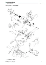
Page 16: ...e device Example The drive belt for the chop and mitre saw KGZ 305 E must be ordered The drive belt has the number 7 in the spare parts drawing 1 By ordering spare parts send a copy of the spare parts drawing 1 with the marked part drive belt and marked positon number 7 to the dealer or spare parts depart ment and provide the following information Type of device Chop and Mitre Saw KGZ 305 E Item n...

Page 17: ...Spare parts KGZ 305 E Version 1 09 EN 17 13 2 Spare parts drawing KGZ 305 E Fig 22 Spare parts drawing KGZ 305 E ...

Page 18: ... Electric motor operated hand held tools transportable tools and lawn and garden machinery Safety Part 3 9 Particular requirements for transportable mitre saws DIN EN 55014 1 2017 Electromagnetic compatibility Requirements for household appliances electric tools and similar apparatus Part 1 Emission DIN EN 55014 2 2015 Electromagnetic compatibility Requirements for household appliances electric to...

Page 19: ...Notes KGZ 305 E Version 1 09 EN 19 15 Notes ...

Page 20: ...www holzstar de ...

Reviews: