Installation of the Chip Extraction Unit
SAA 901 | Version 1.01
11
8 Installation of the Chip Extraction
Unit
i
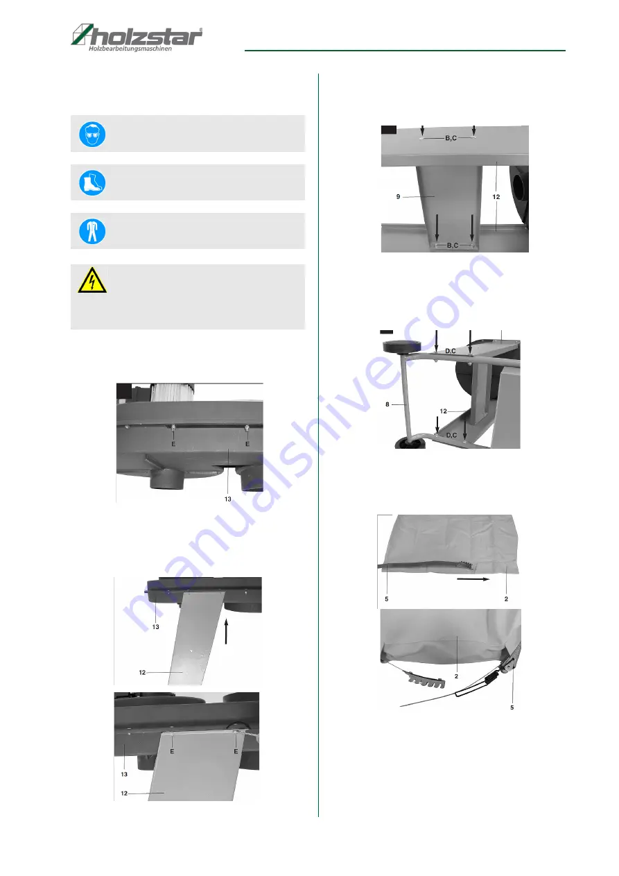
Step 1: Loose the weo nuts (E) on both sides of the
plastic housing (13) Fig.4.
Fig. 4: Plastic housing
Step 2: Slide the side plates (12) over the screws on
the plastic housing (13) and fasten them with
the nuts (E) as shown in Fig.5.
Fig. 5: Mounting side plates
Step 3: Place the stabilizer plate (9) between the side
plates (12) and screw it with the screws (B)
and nuts (C) Fig.6
Fig. 6: Mounting Stabilizer plate
Step 4: Screw the chassis (8) with the screws (D) and
nuts (C) on the side plates (12) as shown in
Fig.7
Fig. 7: Mounting chassis
Step 5: Now thread the quick - release device (5) and
through the guide in the dust bag (2) Fig.8
Fig. 8: Mounting dust bag
Wear protective goggles!
Wear the safety shoes!
Wear the protective clothing!
ATTENTION!
The power plug must be disconnected before any
maintenance changes and assembly work on the
extraction system!


