background image

Machine description

SAA 901 | Version 1.01

9

6 Machine description

6.1 Illustration

Figures in this operation manual serve to provide a basic under-
standing and may differ from the actual design.

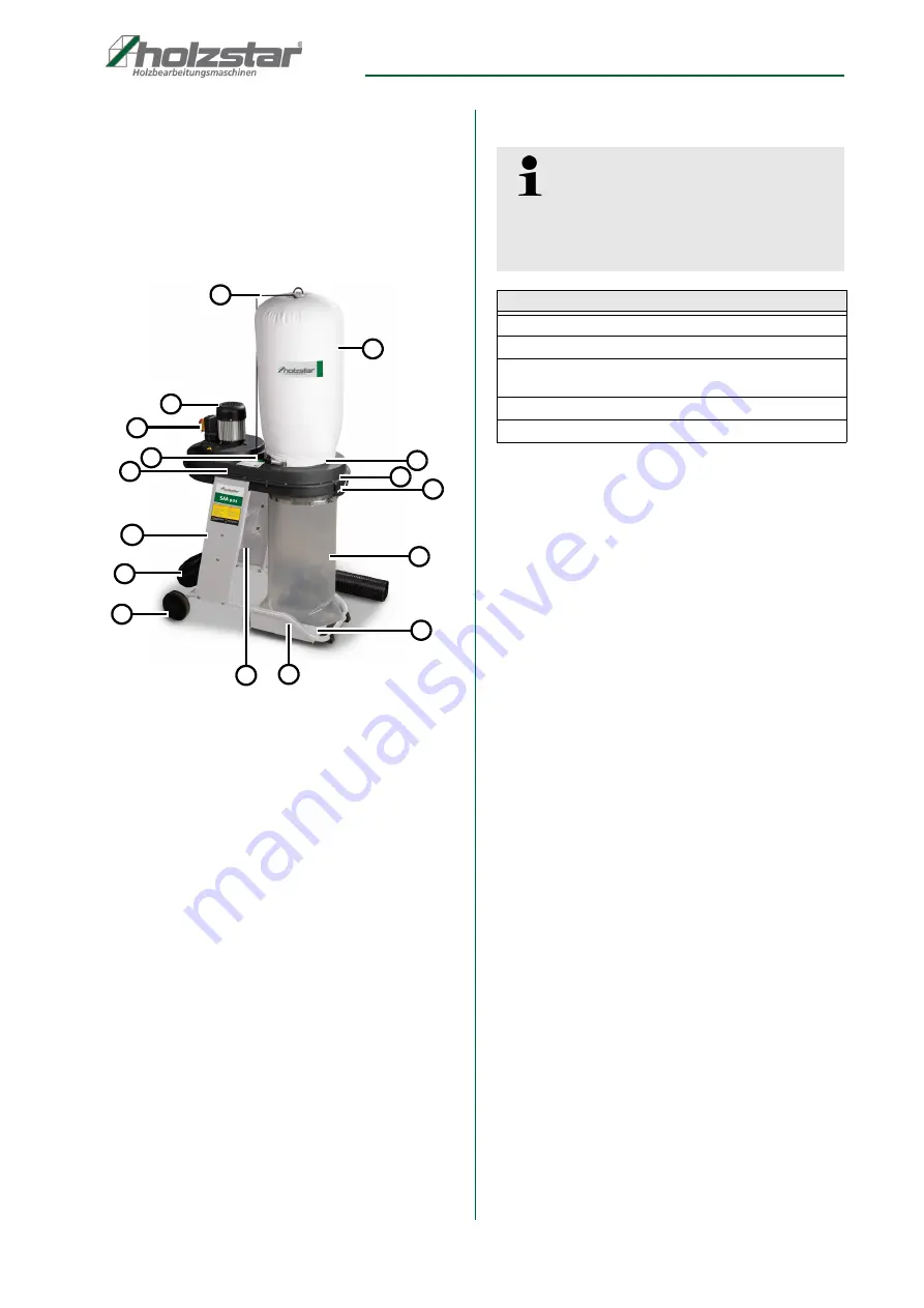
Fig. 3: Chip Extraction Unit SAA 901

  1   Dust bag hook
  2   Dust bag
  3   Quick clamp device for dust bag
  4   Transport handle
  5   Quick clamp device for debris bag
  6   Debris bag
  7   Base plate
  8   Chassis
  9   Strengthening plate
10   Wheels
11   Extraction hose
12   Side plate 
13   Plastic housing
14   Hole for Dust bag
15   ON / OFF Switch
16   Motor

6.2 Scope of supply

1x Hose
2x Clamps

6.3 Optional accessories:


7 Installation and connection

7.1 Requirements to the installation location

Remove the chip extraction unit from its packaging and 
remove all protective foils.

To achieve a good function and a long life of the Chip 
Extraction Unit, the installation location should satisfy 
the following criteria:

- The machine state and machine table must be 

stable, level and free of vibrations ground.

- The installation or worker area must be dry and 

well ventilated.

- The ambient temperature must be within -10 °to + 

50 ° Celsius, max. air humidity 90%.

- It must be sufficient space for the operator, for ma-

terial transport and for adjustment and mainte-
nance work.

- The Chip Extraction Unit must be well grounded. 

Mains voltage and frequency correspond to the 
values of the engine of the machine.

- The installation location must have good illumina-

tion.

1

2

3

4

5

6

7

8

9

10

11

12

13

14

15

16

Tips and recommendations

We recommend using only high-quality original 
Holzstar accessories. Only with original accessories 
can be guaranteed a perfect operation and optimal 
work results.

Designation

PU extraction hose, 

Ø

100 mm

Polyurethane flexible hose, 2,5 / 5  oder 10 m Lengths
Floor cleaning set, incl. 2,5 m spiral hose, extraction 
pipe, floor nozzle with rollers, handle and 2 pipe clamps
Dustbag für SAA 901
Filterbag für SAA 901 

Summary of Contents for SAA 901

Page 1: ...Operating Instructions SAA 901 Chip Extraction Unit SAA 901 SAA 901 ...

Page 2: ...Extraction Unit 5 2 6 General safety aspects 5 2 7 Safety aspects in dealing with electricity 6 2 8 Safety aspects in dealing with application of tools 6 2 9 Safety to operation 7 2 10 Safety aspects on servicing and maintenance 7 2 11 Security check 7 3 Designated use 8 4 Technical Data 8 4 1 Table 8 4 2 Type plate 8 5 Transport packaging storage 8 5 1 Delivery and transport 8 5 2 Packaging 8 5 3...

Page 3: ...e submit any information and experiences you make during application of the machine as these may be valuable for product improvements 1 3 Disclaimer All data in this operation manual has been compiled on the basis of the state of the art valid standards and gui delines as well as our many years of expertise and ex perience The manufacturer shall not be liable for damage in the following cases Fail...

Page 4: ...ipment shall be mandatory Operators shall also be responsible for maintaining the machine in a technically perfect condition For this rea son the following shall apply Operators shall make sure that the maintenance intervals described in these operating instructions are complied with Operators shall regularly check that the safety equipment is fully functional and complete 2 3 Operating staff qual...

Page 5: ...d to the Chip Extraction Unit s Fig 1 and must be obser ved Fig 1 Safety labels 1 Warning of dangerous electrical voltage 2 Safety instructions If safety labels on the machine are damaged or missing this can cause errors personal injury and material damage The safety symbols attached to the machine must not be removed Damaged safety symbols must be replaced immediately As soon as the signs are not...

Page 6: ...ion or servicing of the Chip Extraction Unit is forbidden for people who are less than 18 years or are under influence of alcohol or drugs 13 Check the material to be worked on before starting the Extraction Unit and check about a possible health danger by released dust Take suitable precautions if necessary 14 Protect yourselves from noise by carrying a suitable and admitted hearing protection 15...

Page 7: ...ns must always be covered 12 While working outside good footwear is recommen ded 13 Keep the working area free of rubbish 14 All protective devices must be mounted immediately after servicing 2 10 Safety aspects on servicing and main tenance 1 After servicing repair and cleaning please check whether all protective devices are mounted properly again and no more tools are left inside the machine 2 D...

Page 8: ...the Chip Extraction Unit for visible transport da mage upon delivery In case of visible damage to the Chip Extraction Unit immediately notify the carrier or your retailer 5 2 Packaging All of the Chip Extraction Unit s packaging materials and packing aids are suitable for recycling and must always be disposed of using material based recycling systems Packaging materials made of cardboard must be s...

Page 9: ...ion should satisfy the following criteria The machine state and machine table must be stable level and free of vibrations ground The installation or worker area must be dry and well ventilated The ambient temperature must be within 10 to 50 Celsius max air humidity 90 It must be sufficient space for the operator for ma terial transport and for adjustment and mainte nance work The Chip Extraction U...

Page 10: ... In the follow Steps the Chip Extraction Unit can con nected to the electricity network Schritt 1 The Chip Extraction Unit must be off Schritt 2 The Chip Extraction Unit connect on 230 Volt mains plug with a minimum fuse of 10 A Schritt 3 Check whether all protective devices are mounted Schritt 4 Switch on the Chip Extraction Unit Schritt 5 Check whether the direction of rotation of the motor is c...

Page 11: ... Place the stabilizer plate 9 between the side plates 12 and screw it with the screws B and nuts C Fig 6 Fig 6 Mounting Stabilizer plate Step 4 Screw the chassis 8 with the screws D and nuts C on the side plates 12 as shown in Fig 7 Fig 7 Mounting chassis Step 5 Now thread the quick release device 5 and through the guide in the dust bag 2 Fig 8 Fig 8 Mounting dust bag Wear protective goggles Wear ...

Page 12: ...ening of the plastic housing 13 so that it completely closes the opening and secure it with the quick release device 3 Fig 11 Fig 11 Quick clamp device Dustbag Step 9 Insert a hose attachment A over the suction hose 11 as far as it will go against the suction connection of the appliance and secure it with the hose clamp A as shown in Fig 12 Fig 12 Hose mounting Step 8 If devices with a suction con...

Page 13: ...desired location Fig 14 Chassis 10 Maintenance and Service ATTENTION Pull the Power Plug out Tips and recommendations The Chip Extraction Unit is constructed for efficient operating To guarantee a long life the servicing aspects are to be carried out regularly ATTENTION Danger to life due to electrical shock Danger of live through electric shock by contact with live power components The Chip Extra...

Page 14: ...zardous operating materials from the end of life device If necessary disassemble the machine into assemblies and components that are easy to handle and suitable for recycling Dispose of the machine components andproces sing materials using the intended disposal methods Wear the safety gloves IMPORTANT If one of the following malfunctions occurs immedi ately stop working with the machine Before you...

Page 15: ...panies or from the trader where you have bought the product 13 Spare Parts 13 1 Spare parts orders Spare parts are available from authorised retailers or directly from the manufacturer The contact details have been listed in section 1 2 Customer service Always quote the following key data with your spare parts orders Device type Serial number Quantity Designation Desired shipping type post freight...

Page 16: ...arts 13 2 Spare parts drawing The following drawing are intended to help identify the necessary spare parts To order please send a copy of the part drawing with the marked components to your dealer Fig 15 Spare parts drawing SAA 901 ...

Page 17: ...sion that we have put into circulation with the relevant fundamental health and safety requirements of subsequent EU Directives Relevant EU Directives 2014 30 EU EMC Directive The following harmonized standards have been applied DIN EN ISO 12100 2010 Safety of machinery General principles for design Risk assessment and risk reduction ISO 12100 2010 DIN EN 60204 1 2014 Safety of machinery Electrica...

Page 18: ...www holzstar de ...

Reviews: