background image


47 

6. Maintenance 

6.1 General 

The machine and the entire system must be inspected and maintained at regular intervals. The time limit for 
maintenance is set by the manufacturer and applies to the general conditions of use. The manufacturer should be 
consulted if the system is to be used with corrosive and/or abrasive pumped liquids, as the time limit between 
inspections may need to be reduced.  
 
Note the following information: 


The operating and maintenance manual must be available to the maintenance personnel and its 
instructions followed. Only the repair and maintenance measures listed here may be performed. 


All maintenance, inspection and cleaning work on the machine and the system may only be carried 
out by trained specialists exercising extreme care in a safe workplace. Proper protective clothing is 
to be worn. The machine must be disconnected from the electricity supply before any work is carried 
out. There must be no way that it can be inadvertently switched on. Additionally, the appropriate 
protective measures as defined by the BGV/GNV should be enforced when working in basins and/or 
containers. 


Above a weight of 50kg, only hoisting gear which has been officially approved and which is in a 
technically perfect condition should be used for lowering and raising the machine. 

 
Make sure that all fastening devices, ropes and safety devices of the hand winch are in a technically 
perfect condition. Work may only commence if the auxiliary hoisting gear has been checked and found to 
be in perfect working order. If it is not inspected, danger to personnel may result! 


Wiring work on the machine and system must be carried out by an electrician. For machines 
approved for work in areas subject to explosion danger, please refer to the “Explosion protection in 
accordance with the regulation” chapter.  


When working with inflammable solvents and cleaning agents, fires, unshielded lighting and 
smoking are prohibited. 


Machines which circulate fluids hazardous to health, or which come into contact with them, must be 
decontaminated. It must be ensured that no dangerous gases can form or are present. 


Ensure that all necessary tools and materials are available. Tidiness and cleanliness guarantee safe 
and problem-free operation of the machine. After working on the machine all cleaning materials and 
tools should be removed from it. All materials and tools should be stored in an appropriate place. 


Operating supplies such as oil and lubricants must be collected in appropriate vessels and properly 
disposed of (in accordance with the 75/439/EEC directive and with §§5a, 5b AbfG). Appropriate 
protective clothing is to be worn for cleaning and maintenance jobs. This is to be disposed of in 
accordance with waste code TA 524 02 and EC Directive 91/689/EEC. Only lubricants expressly 
recommended by the manufacturer may be used. Oils and lubricants should not be mixed. Only use 
genuine parts made by the manufacturer. 

 
A trial run or functional test of the machine must be performed as instructed in the general operating 
conditions. 

 Before maintenance or repair disconnect the mixer from the power supply to prevent accidental starting 

of the mixer!


In accordance with the product liability law we point out that we shall not be liable for damages caused by 

our product due to unauthorized repair by persons other than the manufacturer or an authorized workshop or due 
to the use of spare parts other than original HOMA parts. The same product liability limitations are valid for 
accessories.


 Before maintenance or repair make sure that all rotating parts stand still! 

 Before carrying out maintenance and service, the mixer must be thoroughly flushed with clean water. 

 When loosening of the oil chamber control screw, overpressure can escape. Release the screw only 

when pressure balance is secured.


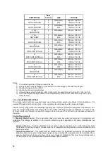
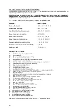
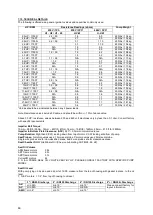
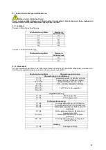
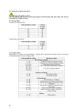
If not otherwise stated, the torque values of the be-low tables should be used.  

Values stated are for clean, lubricated screws.  

Summary of Contents for CHRS Series

Page 1: ...Version 03 2015 No 00510601 01 Original Betriebsanleitung Original Instruction Manual HOMA Pumpenfabrik GmbH Industriestr 1 D 53819 Neunkirchen Seelscheid 60 Hz Baureihe Serie CHRS HRS ...

Page 2: ...ped fluids 38 3 General description 38 3 1 Application 38 3 2 Types of use 38 3 3 Construction 38 4 Package Transport and Storage 41 4 1 Delivery 41 4 2 Transport 41 4 3 Storage 41 4 4 Returning to the supplier 42 5 Installation and Start Up 42 5 1 General 42 5 2 Installation 42 5 3 Start Up 45 5 4 Electrical system 45 5 5 Motor protection 46 5 6 Operation with a static frequency converter 46 5 7 ...

Page 3: ...Low Voltage Directive 06 95 EEC EC Directive explosion prooved operating material 94 9 EEC EC Directive construction products 11 305 EEC Relevant harmonized industrial standards EN 60335 2 41 EN 60335 1 EN 60204 Part 1 EN 61000 6 1 EN 60034 1 EN 61000 6 3 EN 61000 6 2 EN 55014 2 EN 61000 3 3 EN 50014 18 19 20 EN 12050 1 4 EN 61000 6 4 EN 55014 1 EN 61000 3 2 EN ISO 12100 1 and 2 Specially applied ...

Page 4: ...lace costs for the ride of the mechanicians to the location and from the installation place as well as costs for transport are not components of our warranty Hereby arose costs especially costs for checking and transport are bearing by the sender or operator of the pump This is also valid for an asserted warranty claim if a check results that the unit works faultless and is free of defects All pro...

Page 5: ...inated immediately by authorized personnel The product should only be operated if it is in proper working order During the agreed warranty period the product may only be repaired by the manufacturer or an authorized service workshop The manufacturer reserves the right to recall the damaged product to the factory for inspection 1 5 5 Exclusion from liability No liability will be assumed for product...

Page 6: ...ving the product The machine must always be switched off before any work is performed on it assembly dismantling maintenance installation The machine must be disconnected from the electrical system and secured against being switched on again All rotating parts must be at a standstill The operator should inform his her superior immediately should any defects or irregularities occur It is of vital i...

Page 7: ...ces such as soft startup control or frequency drives are used the relay manufacturer s specifications must be followed in order to conform to EMC Special separate shielding measures e g special cables may be necessary for the power supply and control cables The connections may only be made if the relays meet the harmonized EU standards Mobile radio equipment may cause malfunctions Beware of electr...

Page 8: ...pumped fluid differs in regard to composition corrosiveness abrasiveness TS content and many other aspects Generally our products can be used for many applications For more precise details see chapter 3 the machine data sheet and the order confirmation It should be remembered that if the density viscosity or the general composition change this can also alter many parameters of the product When swi...

Page 9: ... Year type test Year type test 12b Declaration of performance Declaration of performance 13 Build year Build year 14 Motor type Motor type 15 IE Marking IE Marking 16 Frequency Frequency 17 Voltage 3 phase Voltage 3 phase 18 Nominal current 3 phase Nominal current 3 phase 19 Motor RPM Motor RPM 20 Voltage Star connection Voltage Star connection 21 Nominal current Star connection Nominal current St...

Page 10: ...de manual pump re start All explosion proof models have both sets of sensors built in as described above with wire ends marked T1 T2 T3 They have to be connected accordingly as described above The temperature sensor set must be connected to the switchgear unit so that it switches off if it overheats Check of Direction of Rotation After the electrical connection has been made check that the agitato...

Page 11: ...unsecured If the product falls over injury can occur The product has to be stored at a place free from vibrations and agitation to avoid damage from the ball bearings We recommend a dry frost protected room with a temperature of between 5 C and 25 C for storage The product may not be stored in rooms where welding work is conducted as the resulting gases and radiation can damage the elastomer parts...

Page 12: ...at lifting gear can be fitted without any trouble since this is required for assembly and removal of the machine The maximum bearing capacity must be greater than the weight of the machine add on units and cable Electric power cables must be laid out in such a way that safe operation and non problematic assembly dismantling are possible at all times The electric power cables should be fastened pro...

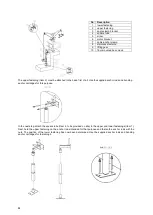
Page 13: ...o the mixer Fasten the mixer to the motor bracket Item 12 as illustrated using two cylinder head screws Item 1 one cylinder head screw Item 2 and the associated U washers Items 3 4 Lay the connecting cable between the pipe clamps Item 6 and screw it to the motor bracket using two cylinder head screws and U washers Items 5 4 Great care should also be taken to ensure that the cable is always laid or...

Page 14: ...tem 1 Next hold the upper fastening on the anchor rods intended for that purpose and fasten the anchor rods with the nuts The position of the lower fastening has now been determined Use the supplied anchor rods and bonding anchor cartridges for fastening it No Description 1 lower fastening 2 upper fastening 3 angle clamp bracket 4 square tube 5 mixer 6 motor bracket 7 cable anchor clamp 8 stainles...

Page 15: ...the mixer is immersed at least half the diameter of the propeller Make sure that all necessary safety precautions have been carried out e g to prevent persons from falling into the tank After longer standstill of the mixer clean the propeller and motor surface from dried remains of mixing liquid in order to prevent cooling problems 5 4 Electrical system Observe the relevant local and national regu...

Page 16: ...in star delta mode is 3 seconds If the motor protection is not installed in the line set the motor protection to the rated current when fully loaded Starting transformer soft start Motor protection should be set to the rated current when fully loaded At partial load we recommend that motor protection is set 5 above the measured current at the operating point The maximum start up time at reduced vo...

Page 17: ...ing agents fires unshielded lighting and smoking are prohibited Machines which circulate fluids hazardous to health or which come into contact with them must be decontaminated It must be ensured that no dangerous gases can form or are present Ensure that all necessary tools and materials are available Tidiness and cleanliness guarantee safe and problem free operation of the machine After working o...

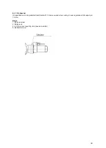
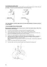
Page 18: ... arise bearings must be replaced at the manu facturer s works The oil in the oil chamber should be changed after every 6000 hours of operation Oil condition Place mixer horizontally so that one of the oil chamber screws is at the top Remove the screw and extract a small amount of oil If the oil is milky or cloudy it indicates a defective shaft seal In this case have the condition of the shaft seal...

Page 19: ...l specification bio degradable Shell Ondina 917 Remove used oil according to local regulations Oil capacity is 1 0 liter Steps 1 Remove screw 2 Release oil 3 4 Fill in correct quantity of oil see below table 5 Re fasten screw ...

Page 20: ...QUIPMENT INVENTORY AND INSPECTION Upon arrival of pump shipment carefully unpack all components and compare with shipping and purchase order documents to ensure that the order is complete Also inspect equipment for any damage that might have occurred in shipment If any problems are detected contact an authorized HOMA customer service immediately 7 4 TRANSPORTATION AND STORAGE PROCEDURE Always lift...

Page 21: ... leads connected to a current regulated control circuit in accordance with NEC 7 5 5 SEAL PROBE WIRING The mechanical seal leak detector probe utilized in the pump is a conductive probe which is normally open The intrusion of water into the seal chamber completes the electrical circuit Control panel provisions will sense this circuit closure and will provide indication or alarm functions depending...

Page 22: ... over tighten Install the profile gasket if not already installed at the factory into the guide claw with the large diameter fitted into the groove inside the claw Refer to the diagram included with the auto coupling kit for proper profile gasket installation Install suitable lifting chain of an adequate size and length to permit proper lowering and raising of the pump Properly locate the base and...

Page 23: ...mension drawing Foundation bolts are to be embedded in the concrete Suction Piping Suction piping should be at least as large as the pump inlet elbow suction If reducers are utilized they should be of the conical type If the liquid source level is below the volute horizontal centerline the reducer must be eccentric and installed with the level side up If the liquid level is above the pump volute h...

Page 24: ... PUMP OPTION The cooling jacket has been supplied based upon the specified operating conditions of this application It is important this jacket is function properly or the internal motor components could become damaged Several cooling configurations are available depending upon customer preference and system requirements You must know what configuration of cooling system is to be used with the pum...

Page 25: ...ped media The water inlet is routed into the jacket s lowest port and returned out of the highest port This option does NOT allow water to enter the pumped media and pump must be ordered from factory this way Required Hardware Mounting a regulating valve pressure gauge and automated block valve between the water supply and the upper jacket port is required The supply valve should be adjusted to al...

Page 26: ...32 Actual system head is higher than calculated or specified 33 Incorrect impeller rotation direction 34 Sump liquid level is below pump s minimum submergence requirement 35 Closed discharge valve or jammed check valve 36 Wear ring s worn If Applicable 37 Vortex at pump s suction 38 Discharge valve partially closed 39 Insufficient NPSHA Dry Pit Application 40 Actual system head is lower than speci...

Page 27: ...any external part that appears worn or damaged 5 SEAL CHAMBER OIL Note Use extreme care when removing the seal chamber plug as the chamber may become pressurized if seal failure has occurred Seal chamber oil should be checked for signs of water intrusion or other impurities any time the pump is removed from wet well To check the condition of the oil remove the oil fill plug Drain the chamber volum...

Page 28: ...e not to damage the sealing surface 10 Verify that seal chamber oil level is within of the indicated value Measurement is from oil level to the top of hole See IOM Manual for seal chamber oil volume if required 11 Remove the new sealing gasket from package and install it onto the seal probe plug 12 Install the seal probe with gasket into the opening taking care not to damage the cable Then tighten...

Page 29: ...uld have the highest current reading Lead Z2 start should have the lowest reading If Z2 current draw is greater than the current draw of either U1 or U2 a smaller size Run capacitor lower microfarad rating is required to correct the condition Example If a 60 µf Run capacitor was supplied change to a 50 µf Run capacitor and check current readings Typically only one step down in capacitor size is re...

Page 30: ...N A 0 5 1 1 400 lbs 181 kg 29HP 1750 P N A 0 4 0 7 500 lbs 227 kg Values should be as indicated between any 2 power leads Note Resistance values include 30 cable and should be within 10 of above value Above 30 HP resistance values between 230 and 460 volt machines very by less than 0 1 ohm Consult factory with specific requirements Impeller Bolt Torque 10mm 26ft lb 35Nm 12mm 45ft lb 61Nm 16mm 108f...

Page 31: ...seinrichtungen sind dann mit dem Lastkabel ausgeführt Aderbezeichnung Motor Überwachungseinrichtung Überwachungen in der Wicklung T1 T2 Temperaturbegrenzer 2 Schalter in Reihe T1 T4 Temperaturregler 2 Schalter in Reihe T1 T2 T3 Temperaturbegrenzer und regler K1 K2 PTC Kaltleiter 3 Kaltleiter in Reihe PT1 PT2 3 x PT100 einzeln ausgeführt PT3 PT4 PT6 PT6 Lagerüberwachung P1 P2 PT100 Lager oben P3 P4...

Page 32: ...ng devices are run from the power cable Cable identification Motor Monitoring system Monitoring in winding T1 T2 Temperature limiter 2 switches in series T1 T4 Temperature controller 2 switches in series T1 T2 T3 Temperature limiter and controller K1 K2 PTC Thermistor 3 thermistors in series PT1 PT2 3 x PT100 individually installed PT3 PT4 PT6 PT6 Bearings monitoring P1 P2 PT100 upper bearing P3 P...

Page 33: ... _____________________ ätzend nein ja welche Stoffe _____________________ mikrobiologisch nein ja welche Stoffe _____________________ explosiv nein ja welche Stoffe _____________________ radioaktiv nein ja welche Stoffe _____________________ sonstige Schadstoffen nein ja welche Stoffe _____________________ Rechtsverbindliche Erklärung Hiermit versichern wir dass die Angaben korrekt und vollständig...

Page 34: ...e no yes which substance __________________ microbiological no yes which substance __________________ explosive no yes which substance __________________ radioactive no yes which substance __________________ other substances no yes which substance __________________ Legally binding declaration We hereby certify that the returned parts have been cleaned carefully To the best of our knowledge they a...

Reviews: