52
7.6. ADDITIONAL PUMP PROTECTIVE DEVICES
Several optional pump protection devices are available to protect submersible motors from damage, and may
have provided in your pump.
Temperature Sensing RTD*: PT100 sensors are available in two critical locations on larger machines, the lower
bearings and motor windings. N.C. Circuit - 108 ohm
Moisture Sensors: Two styles of moisture sensors are available on HOMA pumps.
Moisture Detectors*: These are micro float switches designed to detect small amounts of liquid. These are
available in the stator housing of 50hp and larger size pumps. N.C. Circuit - 268 ohm
Leakage Detectors*: These normally open, single or 2 wire probes are used to detect the presence of water in the
pump. Single wire probes use the pump ground to complete circuit. Optional leak detectors can be installed as
follows:
•
Stator Chamber installation: Probe placed in bottom of stator housing to detect presence of water in the
chamber.
•
Stator or Motor cap installation: Probe used to detect the presence of water only into the stator housing
or motor cap terminal board.
•
Closed loop cooling Installation: Probe placed in stator housing to detect the presence of liquid in the dry
chamber.
* relay is required for sensor operation.
7.7. MECHANICAL INSTALLATION
7.7.1. PUMPS WITH AUTOCOUPLING SYSTEMS
The HOMA Auto-Coupling is a quick removal system used in keeping personnel from having to enter the wet well.
The pump mounts on a stationary base and operates completely or partially submerged (minimum 10” over
volute) in the pumping media.
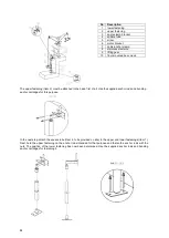
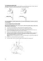
The HOMA Auto-Coupling kit consists of a base, guide claw flange, upper guide rail bracket, profile seal and base
anchor bolts. Refer to dimensional drawing for details.
For all pumps, attach the guide claw flange to the pump discharge flange with the fasteners and gaskets included
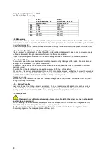
with the auto-coupling kit. Use tightening torque’s indicated in the table below. Do not over tighten! Install the
profile gasket (if not already installed at the factory) into the guide claw with the large diameter fitted into the
groove inside the claw. Refer to the diagram included with the auto-coupling kit for proper profile gasket
installation.
Install suitable lifting chain of an adequate size and length to permit proper lowering and raising of the pump.
Properly locate the base and with the anchor bolts fasten to the floor of the pump station. Make sure when
locating and securing the anchor bolts that the base will align properly with the access cover at the top elevation
of the station. Place the base in position, and level the base.
If the base is not level, proper sealing of the pump to base may not occur!
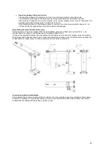
Place the guide rails (supplied by others), cut to length in to the rings of the base. The rails will be secured at the
top of the pump station with the upper guide bar bracket and to extend down to the sump floor.
For stations exceeding 10 feet in depth intermediate guide bar brackets are recommended. One bracket is
recommended for each additional 10 feet of station depth.
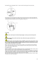
Check that the guide system is properly installed in the vertical orientation by using levels and a plumb line. Fully
tighten all anchors and mounting bolts.
Connect the station riser piping to the outlet flange of the base.
Before lowering the pump, verify the direction of impeller rotation (refer to start-up section for procedure).
Make sure to use lifting equipment that has adequate capacity for the pump that will be handled.
Before
installing pump, check to be certain the profile seal (rubber ring) is properly positioned in the guide claw flange.
Then position pump so the guides on the discharge flange engage the rails. Slowly lower the pump along the
guide rail. Once the pump reaches its bottom location it will automatically connect to the base.
It is recommended that the stationary base elbow be visible before lowering the unit. If this is not possible, ensure
all debris is removed from wet well.
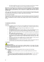
Do not install more than one check valve into any piping system or problems will occur.

