ENGLISH | 11
5.2. Installation
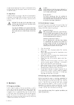
Risk of falling!
When installing the pump and accessories, work is
carried out directly on the water’s edge! Careless-
ness or wearing the wrong shoes can lead to falling.
This is life threatening! Take all safety precautions to
prevent this.
Risque de chute !
Lors de l’installation de la pompe et des accessoires,
les travaux sont effectués directement au bord
de l’eau ! La négligence ou le port de mauvaises
chaussures peuvent entraîner une chute. Ceci pose
un danger de mort ! Prenez toutes les précautions de
sécurité pour éviter cela.
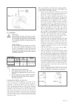
Torque Values:
PUMP MODEL Mounting
Bolts
Anchors
Bolts
Anchors
TORQUE
AUTOCOUPLING
N/A
4
M16
51 Nm / 38 ft lb
RING STAND
4
N/A
5 Nm / 4 ft lb
Notes:
1. Standard anchors are plated steel.
2. Autocoupling systems include qty. 4 M12
anchors for the upper bracket. Torque to 51 Nm
/ 38 ft lb.
3. Anchor bolt holes should be drilled to the actual
diameter of the anchor (M12 anchor requires
12mm diameter hole).
Submerged installation on ring stand
Attach the ring stand (available as an accessory) with
screws to the pump suction nozzle. Mount 90° connec-
tion-elbow or connection loop to the dischargeof the
pump, and mount discharge line. Gate valves and check
valves may need to be installed in accordance with local
regulations. The discharge line must be fitted free of ten-
sion, when using a hose, ensure it is laid kink-free. Secure
the pump by the handle with a cable or chain, and lower it
into the pumping medium. Properly position power cable
and chain so they stay above the pump and cannot enter
the pump suction.
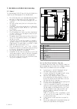
Wet well installation with automatic coupling system
The following instructions apply to the installation of the
original HOMA Autocoupling system:
• Determine the approximate position of the position
of the base elbow and the upper pipe bracket for the
guide tubes, using a plumb bob where necessary.
• Check the correct installation dimensions of the
pump(s) (see dimensional drawings in the appendix).
• Drill mounting holes for the guide rail bracket on the
inside edge of the shaft opening. If this is not possi-
ble due to the space available, the guide rail bracket
can also be mounted in an offset position with a 90°
folded plate on the underside of the shaft cover. Pro-
visionally fasten the guide rail bracket with 2 screws.
• Align the base elbow to the shaft floor, use a plumb
bob from the pipe bracket - the guide tubes must be
exactly perpendicular! Fasten the base elbow to the
wet well floor using anchor bolts. Ensure that the
base elbow is exactly horizontal! If the wet well floor
is uneven, support the bearing surface accordingly.
• Mount the pressure pipes with fittings free of tension
according to the usual mounting principles.
• Insert both guide rails into the eyelets on the base
elbow and cut to size according to the position of the
guide rail bracket. Partially unscrew the guide rails
bracket, insert them into the guide rails and fasten
the bracket. The guide rails must be positioned with
no play at all, otherwise vibration will occur during op-
eration of the pump.
• Clean the wet well of any solid material (debris,
stones, etc.) before commissioning.
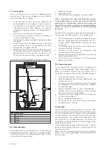
• Mount the guide claw on the pump discharge (thread
or flange connection). Ensure that the rubber profile
gasket is correctly seated in position in the guide claw
(as a seal against the coupling base), so that it will not
fall out when lowering the pump. See graphic below
• Attach the chain to the pump handle or lifting lugs.
Insert the pump with the guide rails in the guide claw
ears. Lower the pump into the wet well. If the pump
is seated on the base elbow, it automatically seals it-
self off to the pressure line and is ready for operation.
• Hang the end of the retrieval chain from a hook at the
wet well opening.
• Hang the motor connection cable of the pump in the
shaft at an appropriate length, with strain relief. Make
sure that the cables can not be bent or damaged.


