14 | ENGLISH
This form is provided for your use in optimizing the perfor-
mance and service life of your single phase pumps, and is
applicable to most Capacitor Start/Capacitor Run motors.
Please contact our customer service with any questions
or if you require any additional information or assistance.
5.7. Direction of rotation
Rotation Direction Check
All pumps have the proper rotation direction when con-
nected to a clockwise field of rotation (U, V, W -> L1, L2,
L3). If the pump rotation is backwards, swap two leads
and reconnect. For smaller pumps, the check can be done
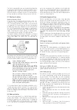
by observing the pump’s movement while starting. To do
this, set the pump lightly on the ground in a perpendicu-
lar fashion and switch it on briefly. When observing from
above, the pump itself moves slightly in a counter-clock-
wise direction when rotating in the right direction.
The correct direction of rotation of the pump is achieved
once the pump moves counter-clockwise, since when
viewed from above, the motor starts in a clockwise di-
rection.
For large pumps, the direction can also be determined by
looking through the pump discharge into the volute. Brief-
ly run the motor in order to verify it is running clockwise.
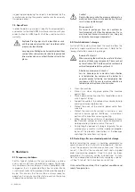
Caution – Rotating Impeller!
Do not touch the rotating impeller or reach into the
volute through the pressure outlets!
Never reach into the volute or touch any rotating
parts during operation. Switch the machine off and
wait until all rotating parts have come to a stop prior
to carrying out maintenance and repair work!
Attention - Turbine en rotation !
Ne pas toucher la turbine en rotation ni pénétrer
dans la volute par les orifices de pression !
Ne jamais mettre la main dans la volute ou toucher
les pièces en rotation pendant le fonctionnement.
Mettre la machine hors tension et attendre l’arrêt de
toutes les pièces en rotation avant d’effectuer des
travaux d’entretien et de réparation !
It is also possible to check the direction of rotation with a
“motor and phase rotation indicator”. This measurement
device is held from the outside up to the motor housing
of the switched-on pump and displays the direction of ro-
tation via an LED.
5.8. Motor protection
The minimum requirement is a thermal relay/motor pro-
tection circuit breaker with temperature compensation,
differential triggering, and reclosing lock in accordance
with VDE 0660 or similar national regulations. If the equip-
ment is connected to power grids where problems often
occur, we recommend the additional use of protective
devices (e.g. overvoltage protection or under voltage pro-
tection or phase failure relays, lightning protection, etc.).
When connecting the machine, the local and legal require-
ments must be adhered to.
5.9. Variable Frequency Drives
Special considerations must be taken when operating
pumps with variable frequency drives (inverters). The in-
verter circuit design, horsepower required by pump, mo-
tor cooling system, power cable length, operating voltage,
and anticipated turndown ratio must be fully evaluated
during the design stage of the installation.
As a minimum, properly sized load reactors and filters
must be installed between the inverter and the pump
to protect the pump motor from damaging voltage
spikes.
Warranty coverage will not be provided on any pump mo-
tor that is operated with a variable frequency drive, unless
the load side of the inverter is properly isolated from the
pump.
5.10. Types of startups
Types of startup using with cables with exposed ends
Direct start up
At full load, the motor protection circuit breaker should
be set to the rated current. In partial load operation it is
recommended to set the motor protection circuit breaker
5% above the measured current at the operating point.
Soft start
At full load, the motor protection should be set to the rat-
ed current. In partial load operation, it is recommended to
set the motor protection 5% above the measured current
at the operating point. The starting time must be max. 5s.
The starting voltage is to be set at 40% of the rated volt-
age according to the rating plate.
Start up with HOMA GO switch
Plug the connector into the socket provided and press the
on/off switch on the GO switch.
5.10.1. After start up
The nominal current is briefly exceeded on start-up. Af-
ter starup, the operating current should not exceed the
nominal current. If the motor does not start immediately
after switching on, it must be shut down immediately. The
applicable startup procedures must be adhered to before
turning on again. If there is a new fault, the machine must
again be shut down immediately. The machine may only
be started up again after troubleshooting. The following
items should be checked:
• Current consumption (permissible deviation between
phases max. 5%)
• Voltage difference between the individual phases
(max. 1%)
• Switching frequency and pauses (see Technical Data)
• Air entry at the inlet - if necessary, a baffle plate must
be attached
• Minimum water coverage, level control, dry run pro-
tection
• Smooth running
• Check for leaks: if necessary, take the necessary
steps according to the chapter “Maintenance”


