ENGLISH | 17
6.4. Sealing chamber
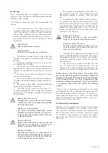
As there are several versions and designs of these mo-
tors, the exact location of the screw plugs varies depend-
ing on the pump unit used.
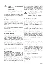
• Slowly and carefully remove the filling plug from the
seal room.
Caution: The oil may be pressurized!
• Remove the drain plug. Drain the oil and collect it in
a suitable reservoir. Clean the drain plug, fit with a
new sealing ring and screw it in again. For complete
drainage, the machine must be slightly tipped on to
its side.
Make sure that the pump is on its side and secure!
• Fill lubricant by means of the opening in the filling
plug. Comply with the specified lubricants and filling
quantities.
• Clean the filling plug, fit with a new sealing ring and
screw it in again.
7. Repairs
7.1. General
When carrying out repair work, the following information
should always be noted:
• Round sealing rings as well as existing seals should
always be replaced.
• Screw fixings such as spring washers should always
be replaced.
• The correct torques must be observed.
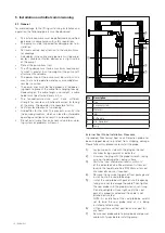
In general, the following applies to repairs:
Switch off the machine, disconnect it from the pow-
er supply (have this done by an electrician), clean it
and place it on a solid base in a horizontal position.
Secure it from falling over and/or slipping.
En général, les dispositions suivantes s‘appliquent
aux réparations :
Éteindre la machine, la débrancher du réseau élec-
trique (faire appel à un électricien), la nettoyer et la
placer sur une base solide en position horizontale.
Éviter qu‘elle ne tombe et/ou ne glisse.
If not otherwise stated, the torque values of the
below tables should be used. Values stated are for clean,
lubricated screws. Fixing torque [ft lbs] for screws A2/A4
(Coefficient of friction = 0.2)
A2/A4,
Hardeness class 70
A2/A4,
Hardeness class 80
DIN912/DIN933
DIN912/DIN933
M6
5 ft lbs
9 ft lbs
M8
12.5 ft lbs
21 ft lbs
M10
24 ft lbs
43 ft lbs
M12
42 ft lbs
73.5 ft lbs
M16
103 ft lbs
180.5 ft lbs
M20
201.5 ft lbs
364.5 ft lbs
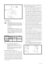
7.2. Changing the impeller and volute
Changing the impeller and the volute.
• Loosen and remove the screws holding the volute to
the oil chamber.
• Secure and remove the volute from the oil chamber
with suitable equipment, e.g. hoisting gear. Place on
a secure base.
• Fasten the impeller with suitable equipment, loosen
and remove the impeller fastening (cylindrical screw
with socket hex).
Pay attention to the locking screw!
• Remove the impeller from the shaft using a suitable
extractor.
• Clean the shaft
• Attach a new impeller to the shaft.
Make sure that the sliding surfaces do not become
damaged!
• Screw a new impeller bolt and clamping disk back
onto the shaft. Fasten the impeller and tighten the
impeller bolt. See table below for toque values.
• Place the motor assembly with impeller back onto
the volute and fasten it with screws.
• It must be possible to turn the impeller by hand.
Impeller Bolt Size
Torque
10mm
35 Nm / 26 ft lb
12mm
61 Nm / 45 ft lb
16mm
146 Nm / 108 ft lb
20mm
285 Nm / 210 ft lb
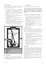
Changing wear ring
The stationary and rotating wear rings determine the gap
between the impeller (rotating wear ring) and the suction
port (stationary wear ring). If this gap is too big, the per-
formance of the machine decreases, and/or it can lead to
ragging or clogging. If the stationary ring shows signs of
wear, it should be replaced. This minimizes wear on the
suction port and and impeller, consequently reducing ex-
pense for spare parts.
Only OEM Parts may be used for replacement!

