


_______________________________________________________User manual Homburg Drain Cleaner type Senior
© Copyright HOMBURG HOLLAND
34
6.2
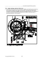
Operation
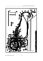
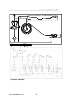
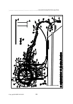
The tractor pto drives the diaphragm water pump. Through the suction basket and the
suction hose water is sucked in from a ditch or a water tanker. Then the water is sent
through a pressure controller (the excess pressure is sent back through an overflow
hose to the ditch or the water tanker) and then through the rotating centre of the
flushing hose reel, after which it sprays out of the nozzle and performs its cleaning
action in the drainpipe. The flushing hose runs from the reel with the drive mechanism
through the guide arm and roller bend into the drainpipe.
See diagram fig. 52.
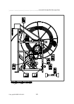
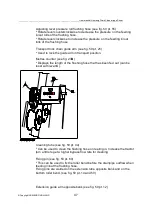
The guide arm can be folded in and out with the aid of two hydraulic cylinders from
vertical to horizontal position and back. The guide arm can be extended and retracted
with the aid of a fourth cylinder. A third cylinder is used to slew the guide arm. The
flushing hose can be fed through the guide arm and the roller bends with the aid of 4
rubber wheels driven by two hydraulic motors that are clamped around the flushing
hose. The hydraulic system is designed in such a manner that both during feeding in
and feeding out the reel wants to roll up under slight pressure, so the flushing hose
always winds tightly around the reel. See hydraulic diagram fig. 53.
The flushing hose guide of this machine is driven mechanically and it ensures that the
flushing hose winds evenly on the reel. The bottom roller bend can be turned to enable
cleaning drainpipes in the own bank as well as in the opposite bank. Various options as
described in this manual are available for the machine.
The hydraulic system of the machine features a pressure compensation valve that
sends the excess oil from the tractor directly back to the hydraulic reservoir of the
tractor. That reduces the heat generation of the hydraulic oil. In addition, the hydraulic
system is equipped with a pressure relief valve, a pressure gauge, and a speed control
valve that can be used to set the machine operating speed. See hydraulic diagram fig.
53.
The front of the machine is the side facing the tractor. The guide arm can only be
unfolded to the right of the machine. That means the drainpipes to be cleaned must
always be kept to the right of the machine.
In areas without ditches in which the drainpipes end, they end in concrete wells. Then
the machine must be equipped with an optional wells set. This wells set is composed of
a 2 metres long pipe and a 30° knee that are mounted between the top and bottom
roller bends.
Summary of Contents for SE-M135
Page 2: ......
Page 97: ......
Page 99: ......
Page 100: ......
Page 101: ......
Page 102: ......
Page 103: ......
Page 104: ......
Page 105: ......
Page 106: ......
Page 107: ......
Page 108: ......
Page 112: ......
Page 113: ......
Page 114: ......
Page 115: ......
Page 116: ......
Page 117: ......
Page 118: ......
Page 119: ......
Page 120: ......


