background image

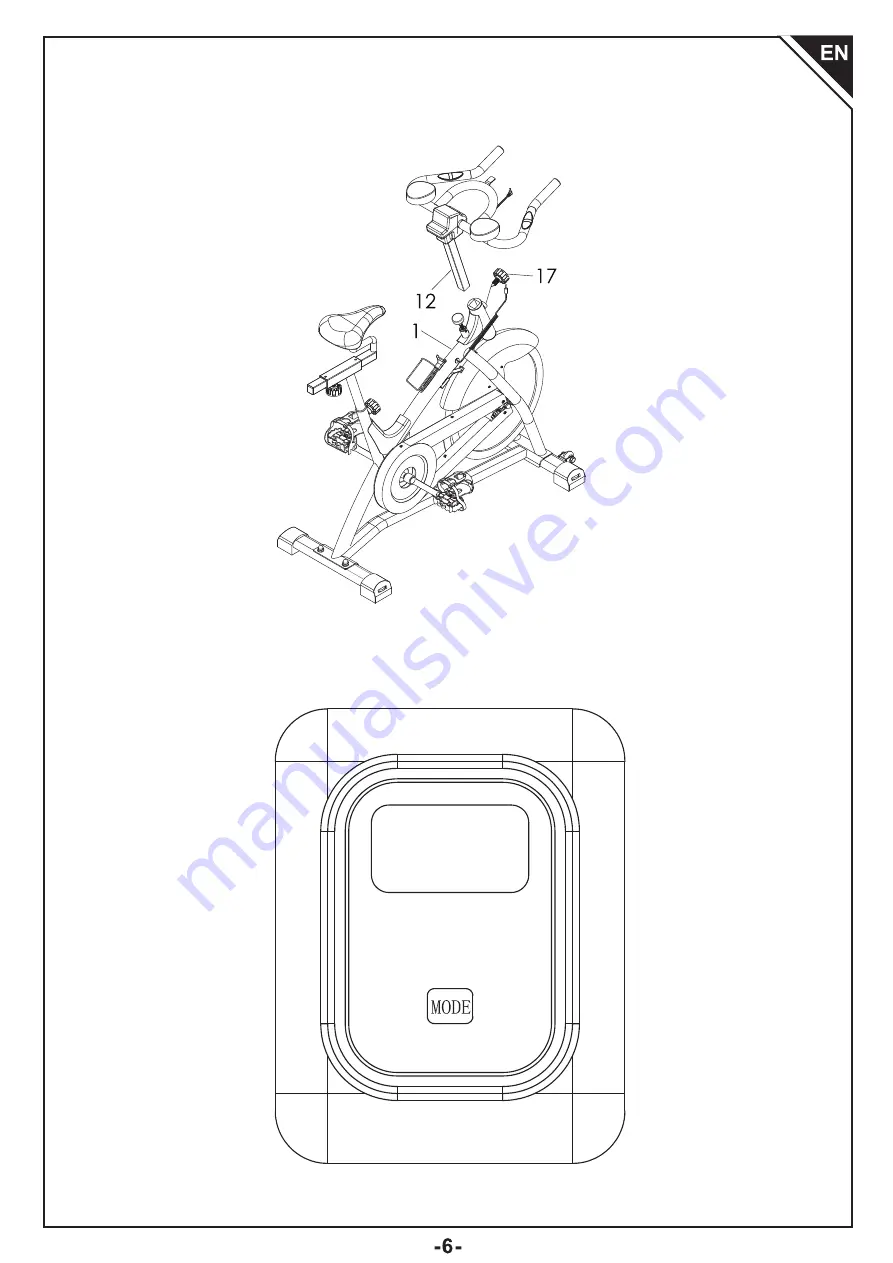
Step 6

Install the handlebar (12) on the main frame (1), and stabilize with the adjustment knob (17).

Control Panel

Summary of Contents for A90-254

Page 1: ...ASSEMBLY INSTRUCTION MANUAL INaoa008V01_UK IMPORTANT RETAIN FOR FUTURE REFERENCE READ CAREFULLY A90 254...

Page 2: ...e please contact our support team with your product model number and Amazon order number Included 1 x Handlebar 1 x Handlebar post 1 x Handlebar cover 1 x Bike seat 1 x Saddle tube 1 x Seat post 1 x E...

Page 3: ...n you have to stop movements immediately 5 Please do not use the product in a humid environment like a bathroom otherwise this would lead to safety hazards easily 6 Supervision is necessary if users a...

Page 4: ...Product Assembly Step1 Install the front stabilizing foot 2 and the rear stabilizing foot 3 on the main frame 1 then tighten with 2 M10 45 carriage bolts 59 2 M10 flat washers 34 and 2 M10 cap nuts 60...

Page 5: ...20 on the crank arm R 21 and crank arm L 22 respectively Note L stands for left and R stands for right Step 3 Install the bike seat 10 on the seat post 8 Then install the seat post 8 on the saddle tub...

Page 6: ...he handlebar 11 on the handlebar post 12 and stabilize with 4 M8 15 inner hexagonal screws 69 4 M8 flat washers 48 and 4 M8 anti loose nuts 70 Install the upper handlebar cover 13 on the handle bar 11...

Page 7: ...Step 6 Install the handlebar 12 on the main frame 1 and stabilize with the adjustment knob 17 Control Panel...

Page 8: ...lay current speed 4 DISTANCE Display the distances from exercise start to end 5 ODOMETER Monitor will display the total accumulated distance after the battery is reinstalled the value will return to z...

Page 9: ......

Page 10: ......

Reviews: