background image

Operation (continued)

18

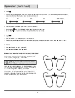
WARM/COOL WEATHER OPERATING INSTRUCTIONS

Speed settings for warm or cool weather depend on factors such
as the room size, ceiling height, number of fans.

Warm weather - (Counterclockwise Direction) A downward air flow 
creates a cooling effect. This allows you to set your air conditioner 
on a warmer setting without affecting your comfort.

Cool weather - (Clockwise Direction) An upward air flow moves 
warm air off the ceiling. This allows you to set your heating unit on 
a cooler setting without affecting your comfort.

NOTE:


The fan reverse buttons must be pressed while the 

fan is running.

4.     Timer

     Pressing the timer buttons will automatically turn fan and light (if light is on) off after 2, 4, or 8 hours. When you activate the timer 

mode, the LED to the left of the time above the clock will illuminate.

Off   


 2H          


4H         


8H    


Disables timer

6.     Light

    Press and release the light button to turn the light on or off.

    Light on: The fan memory function will resume the light setting (on or off and dim) on the fan prior to the power being turned off.

7.    Dimmer

    Press      to increase the desired light level.

    Press      to decrease the desired light level.

5.     Fan reverse button (Must be pushed when the fan is in operation)

    Warm weather:      LED bar will illuminate and the lights will flow from high to low.

    Cool weather:       LED bar will illuminate and the lights will flow from low to high.

Summary of Contents for 1001689569

Page 1: ...1001689569 Model YG493OD EB Questions problems missing parts Before returning to the store call Home Decorators Collection Customer Service 1 800 986 3460 HOMEDEPOT COM HOMEDECORATORS THANK YOU THANK...

Page 2: ...ice Parts 16 16 16 17 18 19 19 21 Table of Contents 2 Table of Contents Safety Information Warranty Pre Installation Tools Required Hardware Included Package Contents Dual Mounting Instructions Instal...

Page 3: ...d carefully up into the outlet box The wires should be spread apart with the grounded conductor and the equipment grounding conductor on one side of the outlet box and ungrounded conductor on the othe...

Page 4: ...not be considered a defect Servicing performed by unauthorized persons shall render the warranty invalid There is no other express warranty We hereby disclaim any and all warranties including but not...

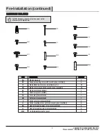
Page 5: ...washer preassembled Clevis pin preassembled Cotter pin preassembled Cross pin preassembled Setscrew preassembled Collar setscrew preassembled Collar mounting screw with lock washer preassembled Light...

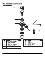
Page 6: ...ate 14 watt LED Light kit Glass shade Remote control Quantity Quantity 8 8 1 1 1 1 Part Part A B C D E F G Quantity Quantity 1 1 1 1 1 1 1 Description Description Mounting bracket preassembled Canopy...

Page 7: ...ard downrod installation the distance from the ceiling to the bottom of the fan blades will be approximately 12 in The close to ceiling installation reduces the distance from the ceiling to the bottom...

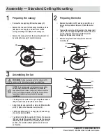
Page 8: ...ree different ways to mount the outlet box NN not included NN NN OO NN NN A Installation MOUNTING OPTIONS MOUNTING OPTIONS WARNING To reduce the risk of fire electric shock or personal injury mount th...

Page 9: ...ld result in the fan loosening and possibly falling Carefully feed the motor wires up through the downrod RR Thread the downrod RR into the collar Align the holes and replace the clevis pin EE and cot...

Page 10: ...y loosening the four canopy mounting screws BB on the top of the canopy C Remove the two non slotted canopy mounting screws BB and loosen the slotted canopy mounting screws BB Remove the canopy bottom...

Page 11: ...ng system marked acceptable for fan support and use the mounting screws provided with the outlet box WARNING The tab in the ring must rest in the groove of the hanger ball E Failure to properly seat t...

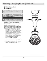
Page 12: ...from the hanger ball downrod assembly E When using close to ceiling mounting there is only one green ground lead from the mounting bracket A since the hanger ball downrod assembly E is not used Conne...

Page 13: ...as an aid to mounting Do not leave the fan assembly unattended until all four canopy mounting screws BB are engaged and firmly tightened Slide the canopy C up to the ceiling Make sure you have placed...

Page 14: ...emaining blade arms I G H I DD Attach the blades H to the blade arms I using the three blade attachment screws and rubber washers CC Start a screw with fiber washer CC into the blade arms I but do not...

Page 15: ...lation disconnect the power by turning off the circuit breaker or removing the fuse at the fuse box Turning power off using the fan switch is not sufficient to prevent electric shock Remove one of the...

Page 16: ...n may begin spinning and the down light if applicable will blink multiple times The fan will dismiss all other remotes LEARNING PROCESS MM M Timer Fan on off Light on off Decreases the light level Dim...

Page 17: ...mfort BreezeTM mode will automatically cancel the Comfort BreezeTM mode and resume normal fan operation 3 Comfort BreezeTM There are three Comfort BreezeTM settings Pressing the button will activate t...

Page 18: ...ile the fan is running 4 Timer Pressing the timer buttons will automatically turn fan and light if light is on off after 2 4 or 8 hours When you activate the timer mode the LED to the left of the time...

Page 19: ...the electrical panel box before you attempt any repairs Refer to the section Making the Electrical Connections on page 12 Problem Problem Solution Solution Check the main and branch circuit fuses or b...

Page 20: ...ter of the selected blade to the point on the ceiling Rotate the fan until the next blade is positioned and repeat the measurement using the same point from the ceiling for every blade Measurement dev...

Page 21: ...ol Part Part AA BB CC DD EE FF GG HH II JJ KK LL MM Description Description Plastic wire nut Canopy mounting screw with washer preassembled Blade attachment screw and fiber washer Blade arm screw and...

Page 22: ...ts Before returning to the store call Home Decorators Collection Customer Service 8 a m 7 p m EST Monday Friday 9 a m 6 p m EST Saturday 1 800 986 3460 HOMEDEPOT COM HOMEDECORATORS Retain this manual...

Reviews: