background image

 2 

HOMEDEPOT.COM/HOMEDECORATORS 


Please contact 1-800-986-3460 for further assistance. 


Table of Contents 


Table of Contents .......................................................... 2


Safety Information ......................................................... 2


Specifications ................................................................ 3 
Warranty ......................................................................... 3


Pre-installation .............................................................. 3


Planning Installation ................................................................3


Tools Required .........................................................................4


Hardware Included ...................................................................4


Package Contents ....................................................................5


Installation – Mounting Options

……………….......…………

Installation 

……………….......………………………………………..

7       

Operation ..................................................................... 10   


Preparing the Remote Control .................................. 11   


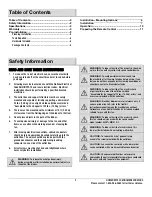
Safety Information 


READ AND SAVE THESE INSTRUCTIONS 

1. 

To reduce the risk of electric shock, ensure the electricity 
has been turned off at the circuit breaker or fuse box before 
you begin. 


2.     All wiring must be in accordance with the National Electrical 

Code ANSI/NFPA 70 and local electrical codes. Electrical 
installation should be performed by a qualified licensed 
electrician. 

 
3.     The outlet box and support structure must be securely 

mounted and capable of reliably supporting a minimum of 
35 lbs. (15.9 kg). Use only UL-listed outlet boxes marked 
“Acceptable for Fan Support of 35 lbs. (15.9 kg) or less.” 

 
4.     The fan must be mounted with a minimum of 10 ft (3.05 m) 

of clearance from the trailing edge of the blades to the floor. 

 
5.     Do not place objects in the path of the blades. 

 
6.     To avoid personal injury or damage to the fan and other 

items, use caution when working around or cleaning the 
fan. 

 
7.     After making electrical connections, spliced conductors 

should be turned upward and pushed carefully up into the 
outlet box. The wires should be spread apart with the 
grounded conductor and the equipment-grounding 
conductor on one side of the outlet box. 

 
8.     All set screws must be checked and retightened where 

necessary before installation. 


WARNING: 

To reduce the risk of fire or electric shock, do 

not use this fan with any solid-state speed control device. 


WARNING: 

To avoid possible electrical shock, turn 

the electricity off at the main fuse box before wiring. If you 
feel you do not have enough electrical wiring knowledge or 
experience, contact a licensed electrician. 


WARNING: 

To reduce the risk of fire, electric shock 

or personal injury, mount to outlet box marked 
“Acceptable for fan support of 35 lbs. (15.9 kg) or less”, and 
use screws provided with the outlet box. 


WARNING: 

Electrical diagrams are for reference only. If 

you are using a light kit, refer to the light kit 
instructions manual to make the electrical connections. 
Optional use of any light kit shall be UL-listed and marked 
suitable for use with this fan. 


WARNING: 

To reduce the risk of fire or electric shock, 

this fan should only be used with fan speed control 
model number E08BT+MR181A-3.


WARNING: 

To reduce the risk of electric shock, this 

fan must be installed with an isolating wall switch.


CAUTION: 

To reduce the risk of personal injury, 

use only the screws provided with the outlet box.


CAUTION: 

Fan cannot be controlled with a dimmer but 

can be controlled with a wall mounted fan speed control.


CAUTION: 

Changes or modifications not expressly 

approved by the party responsible for compliance could void 
the user’s authority to operate the equipment. 


WARNING: 

To reduce the risk of personal injury, 

during assembly or after installation, do not insert objects in 
the path of the blades. 

Summary of Contents for 1004 552 791

Page 1: ...f products available for your home improvement needs Thank you for choosing Home Decorators Collection Item 1004 552 791 1004 552 804 1004 552 801 Model 7982HDCBN 7982HDCGL 7982HDCVB USE AND CARE GUIDE 21 5 IN INDOOR COVERED OUTDOOR CEILING FAN Questions problems missing parts Before returning to the store call Home Decorators Collection Customer Service 8 a m 7 p m EST Monday Friday 9 a m 6 p m E...

Page 2: ... equipment grounding conductor on one side of the outlet box 8 All set screws must be checked and retightened where necessary before installation WARNING To reduce the risk of fire or electric shock do not use this fan with any solid state speed control device WARNING To avoid possible electrical shock turn the electricity off at the main fuse box before wiring If you feel you do not have enough e...

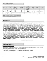
Page 3: ... of this type give their longest useful life when protected from varying weather conditions A certain amount of wobble is normal and should not be considered a defect Servicing performed by unauthorized persons shall render the warranty invalid There is no other express warranty Home Decorators Collection hereby disclaims any and all warranties including but not limited to those of merchantability...

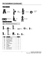
Page 4: ...cal tape Safety glasses Drill Wire stripper HARDWARE INCLUDED NOTE Hardware not shown to actual size AA CC DD EE FF BB GG HH JJ KK Part Description Quantity AA 8 32 x 1 1 2 Screw 2 BB Lock washer 8 32 2 CC 8 X 1 1 2 Screw 2 DD Spring washer 1 8IP 2 EE Flat washer 4 FF 8 32 x 1 4 Screw 2 GG Plug pin 1 HH R shaped pin 1 JJ Wire Nut 6 KK 8 32 x 3 8 Screw 1 LL M4 x 5 16 Screw 2 LL ...

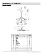
Page 5: ...installation continued PACKAGE CONTENTS Part Description Quantity A Mounting bracket inside canopy 1 B Downrod 1 C Canopy 1 D Cover 1 E Cage 1 F LED bulbs 4 G Metal grill 1 H Knurled screws 4 J Hanger ball 1 K Remote control 1 L Fan blade 1 M Receiver 1 N Bottom plastic cover 1 O Filter 1 ...

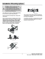
Page 6: ...ct the power by removing the fuses or turning off the circuit breakers Secure the outlet box directly to the building structure Use the appropriate fasteners and materials The outlet box and support structure must be securely mounted and capable of reliably supporting a minimum of 35 lbs 15 9kg Use only UL listed outlet boxes marked Acceptable for fan support of 35 lbs 15 9 Kg or less Do not use a...

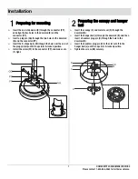
Page 7: ... and the connector PP Insert the R shaped pin HH though the hole near the end of the plug pin GG until it snaps into its locked position Install the screw FF to the connector PP and make sure it s tight Insert the canopy C and metal cover D through the downrod B Insert the hanger ball J through the downrod B and then insert a headless plug pin Q through the hole in the downrod B Insert the headles...

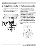
Page 8: ...nopy C If you do not wish to cut the wires you will need to neatly wrap them Connect the fan motor blue wires to the receiver M blue using a wire nut JJ the fan motor white wires to the receiver M white wire using a wire nut JJ and the fan motor black wires to the receiver M black wire using a wire nut JJ Connect the receiver M white wires to the filter O white wire using a wire nut JJ and the rec...

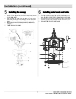
Page 9: ...s FF in the mounting bracket A Push up to engage the slots and to lock in place Rotate the metal cover D clockwise to lock in the bottom of the canopy C Tighten the screws LL securely Insert the fan blades L though the shaft U install bottom plastic cover N onto the fan shaft after the blade assembly L is installed Align the locking slots of the metal grill G with three knurled screws H in the cag...

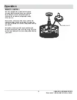
Page 10: ...ctors such as the room size ceiling height number of fans and so on Warm weather Forward push the reverse switch to left A downward airflow creates a cooling effect This allows you to set your air conditioner on a warmer setting without affecting your comfort Cool weather Reverse push the reverse switch to right An upward airflow moves warm air off of the ceiling This allows you to set your heatin...

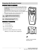
Page 11: ...he control of ceiling fan and in an AC110 120V 60Hz power supply only Do not install in damp locations or immerse in water For indoor use only Do not pull on or cut leads shorter Do not drop or bump the unit CAUTION To reduce the risk of fire or injury do not use this product in conjunction with any variable rheostat wall control NOTE The remote control has already been paired to the ceiling fan f...

Page 12: ...ssing parts Before returning to the store call Home Decorators Collection Customer Service 8 a m 7 p m EST Monday Friday 9 a m 6 p m EST Saturday 1 800 986 3460 HOMEDEPOT COM HOMEDECORATORS Retain this manual for future use ...

Page 13: ...os besoins Merci d avoir choisi Home Decorators Collection Article n 1004 552 791 1004 552 804 1004 552 801 Modèle n 7982HDCBN 7982HDCGL 7982HDCVB GUIDE D UTILISATION ET D ENTRETIEN VENTILATEUR DE PLAFOND D INTÉRIEUR COUVERT EXTÉRIEUR 21 5 PO Des questions des problèmes ou des pièces manquantes Avant de retourner au magasin appelez le service clientèle Home Decorators Collection entre 8 et 19 h he...

Page 14: ...vant installation AVERTISSEMENT Pour réduire le risque de départ de feu ou de choc électrique ne pas utiliser ce ventilateur avec tout régulateur de vitesse à semi conducteurs AVERTISSEMENT Pour éviter tout choc électrique couper l électricité à la boîte de fusibles principale avant de procéder au câblage Si l utilisateur ne pense pas avoir de connaissances ou d expérience suffisantes dans les bra...

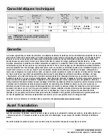
Page 15: ...nis en laiton de ce type offrent une durabilité maximale lorsqu ils sont protégés des différentes conditions climatiques Un léger tremblement est normal et ne doit pas être considéré comme un défaut Une réparation effectuée par une personne non autorisée invalidera la garantie Il n y a pas d autre garantie expresse Home Decorators Collection se dégage par les présentes de toutes garanties y compri...

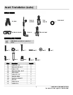
Page 16: ...Perceuse Pince à dénuder QUINCAILLERIE FOURNIE REMARQUE Quincaillerie non représentée à l échelle Pièce Description Quantité AA Vis 8 32 x 1 1 2 2 BB Rondelle d arrêt 8 32 2 CC Vis 8 x 1 1 2 2 DD Rondelle élastique 1 8 IP 2 EE Rondelle plate 4 FF Vis 8 32 x 1 1 4 2 GG Goupille bouchon 1 HH Goupille en forme de R 1 JJ Serre fils 6 KK Vis 8 32 x 3 8 1 LL Vis M4 x 5 16 2 AA CC DD EE FF BB GG HH JJ KK...

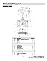
Page 17: ...NTENU DU PAQUET Pièce Description Quantité A Support de fixation sous le couvercle 1 B Tige 1 C Couvercle 1 D Cache vis 1 E Cage 1 F Ampoules DEL 4 G Grille métallique 1 H Vis moletées 4 J Boule de suspension 1 K Télécommande 1 L Pale de ventilateur 1 M Récepteur 1 N Couvercle en plastique du bas 1 O Filtre 1 ...

Page 18: ... la charpente du bâtiment Utiliser les attaches et le matériel appropriés La boîte de sortie et la structure de soutien doivent être solidement montées et capables de soutenir 35 lb 15 9 kg minimum Utiliser seulement des boîtes de sortie homologuées UL marquées Acceptable for Fan Support of 35 lbs 15 9 kg or less Ne pas utiliser de boîte de sortie en plastique Les illustrations ci dessous montrent...

Page 19: ... en forme de R HH dans le trou près de l extrémité de la goupille bouchon GG jusqu à ce qu elle s enclenche en position verrouillée Monter la vis FF sur le connecteur PP et s assurer qu elle est bien serrée Enfiler le couvercle C et le couvercle métallique D dans la tige B Enfiler et faire descendre la boule de suspension J sur la tige B puis enfiler une goupille bouchon sans tête Q dans de la tig...

Page 20: ...ur sur le fil bleu du récepteur M avec un serre fils JJ le fil blanc du moteur du ventilateur sur le fil blanc du récepteur M avec un serre fils JJ et le fil noir du moteur du ventilateur sur le fil noir du récepteur M avec un serre fils JJ Raccordez les fils blancs du récepteur M au fil blanc du filtre O à l aide d un capuchon de connexion JJ et les fils noirs du récepteur M au fil noir du filtre...

Page 21: ...vers le haut pour enclencher les fentes et verrouiller en place Tourner le couvercle métallique D dans le sens horaire pour verrouiller le bas du couvercle C Resserrer les vis LL en toute sécurité Insérer les pales de ventilateur L dans l arbre U puis installer le couvercle en plastique du bas N sur l arbre du ventilateur une fois l ensemble des pales L installé Aligner les fentes de verrouillage ...

Page 22: ...eur de plafond le nombre de ventilateurs etc Temps chaud Marche avant pousser le commutateur vers la gauche Un flux d air descendant a un effet refroidissant Ceci permet de régler le conditionneur d air à une température supérieure sans nuire au confort des occupants Temps froid Marche arrière pousser le commutateur vers la droite Un flux d air ascendant éloigne l air chaud du plafond Ceci permet ...

Page 23: ...tilateur de plafond et sur du 110 120 V c a 60 Hz seulement Ne pas l installer dans un lieu humide ni le plonger dans l eau Réservé à une utilisation à l intérieur Ne pas tirer sur les fils ni les raccourcir Ne pas le faire tomber ni cogner l appareil ATTENTION Pour réduire le risque de départ de feu ou de blessure ne pas utiliser ce produit en conjonction avec une quelconque commande murale varia...

Page 24: ... de retourner au magasin appelez le service clientèle Home Decorators Collection entre 8 et 19 h heure de l Est du lundi au vendredi 9 et 18 h heure de l Est le samedi 1 800 986 3460 HOMEDEPOT COM HOMEDECORATORS Conservez ce manuel pour une utilisation future ...

Page 25: ...oramiento del hogar Gracias por elegir Home Decorators Collection Artículo n º 1004 552 791 1004 552 804 1004 552 801 Modelo n º 7982HDCBN 7982HDCGL 7982HDCVB GUÍA DE USO Y CUIDADO VENTILADOR DE TECHO PARA INTERIORES EXTERIORES CUBIERTO DE 21 5 Tiene preguntas o problemas o le faltan piezas Antes de devolver a la tienda llame a Servicio al Cliente de Home Decorators Collection Lunes a viernes de 8...

Page 26: ...lver a ajustarlos según sea necesario antes de la instalación ADVERTENCIA Para reducir el riesgo de incendio o descarga eléctrica no use este ventilador con ningún dispositivo de control de velocidad de estado sólido ADVERTENCIA Para evitar posibles descargas eléctricas corte la electricidad en la caja de fusibles principal antes de realizar el cableado Si considera que no posee suficientes conoci...

Page 27: ... Este tipo de acabado de latón tendrá una vida útil más extensa si se protege de las condiciones variables del clima Un cierto bamboleo es normal y no se considerará un defecto Si una persona no autorizada repara este artículo se anulará la garantía No existe otra garantía expresa Por la presente Home Decorators Collection renuncia a todas las garantías incluidas entre otras las garantías de comer...

Page 28: ...eguridad Taladro Alicates pelacables HERRAJE INCLUIDO NOTA El herraje no se muestra en su tamaño real Pieza Descripción Cantidad AA Tornillo 8 32 x 1 1 2 2 BB Arandela de seguridad 8 32 2 CC Tornillo 8 x 1 1 2 2 DD Arandela de presión 1 8IP 2 EE Arandela plana 4 FF Tornillo 8 32 x 1 4 2 GG Pasador de chaveta 1 HH Pasador R 1 JJ Conector de torsión 6 KK Tornillo 8 32 x 3 8 1 LL Tornillo M4 x 5 16 2...

Page 29: ...uación CONTENIDO DEL PAQUETE Pieza Descripción Cantidad A Soporte de montaje dentro de la cubierta 1 B Varilla de bajada 1 C Cubierta 1 D Tapa 1 E Jaula 1 F Bombilla LED 4 G Rejilla de metal 1 H Tornillos estriados 4 J Bola colgante 1 K Control remoto 1 L Aspa del ventilador 1 M Receptor 1 N Tapa plástica inferior 1 O Filtro 1 ...

Page 30: ...dificio Use los elementos de fijación y materiales adecuados La caja del tomacorriente y la estructura de soporte se deben montar de forma segura además deben ser capaces de soportar como mínimo 35 lb 15 9 kg Solo debe usar cajas de tomacorriente con certificación UL con la etiqueta Aceptable para soporte de ventilador de 35 lb 15 9 kg o menos No use una caja de tomacorriente plástica Las siguient...

Page 31: ...or PP Inserte el pasador R HH a través del orificio cerca del extremo del pasador de chaveta GG hasta que encaje en la posición de bloqueo Instale el tornillo FF al conector PP y asegúrese de que esté apretado Inserte la cubierta C y la tapa de metal D a través de la varilla de bajada B Inserte la bola colgante J a través de la varilla de bajada B y luego inserte un pasador de chaveta sin cabeza Q...

Page 32: ... azul receptor M con un conector de torsión JJ los cables blancos del motor del ventilador al cable blanco del receptor M con un conector de torsión JJ y los cables negros del motor del ventilador al cable negro del receptor M con un conector de torsión JJ Conecta los cables blancos del receptor M al cable blanco del filtro M usando una tuerca de conexión de cables JJ y los cables negros del recep...

Page 33: ...je A Empuje hacia arriba para encajar las ranuras y fijarlas en su lugar Rote la tapa de metal D en sentido horario para bloquearla en la parte inferior de la cubierta C Apriete firmemente el tornillo LL Inserte las aspas del ventilado L a través del eje U instale la tapa plástica inferior N en el eje del ventilador después de instalar al conjunto de las aspas L Alinee las ranuras de bloqueo de la...

Page 34: ...ra del techo la cantidad de ventiladores etc Clima cálido giro hacia delante lleve el interruptor de reversa hacia la izquierda Un flujo de aire hacia abajo que crea un efecto de enfriamiento Esto le permite configurar un ajuste más cálido en el aire acondicionado sin afectar su confort Clima frío giro hacia atrás lleve el interruptor de reversa hacia la derecha Un flujo de aire ascendente que mue...

Page 35: ...ar para controlar el ventilador de techo y solo con una fuente de alimentación de 110 120 V CA 60 Hz No instale en ubicaciones húmedas ni sumerja en agua solo para usar en interiores No jale ni corte los cables No deje caer ni golpee la unidad PRECAUCIÓN Para reducir el riesgo de incendio o lesiones no use este producto junto con ningún control variable reóstato de pared NOTA Ya se ha sincronizado...

Page 36: ...tes de devolver a la tienda llame a Atención al Cliente de Home Decorators Collection Lunes a viernes de 8 00 a m a 7 00 p m EST y los sábados de 9 00 a m a 6 00 p m EST 1 800 986 3460 HOMEDEPOT COM HOMEDECORATORS Guarde este manual para su uso futuro ...

Reviews: