background image

5

HOMEDEPOT.COM/HOMEDECORATORS

Please contact 1-800-986-3460 for further assistance.

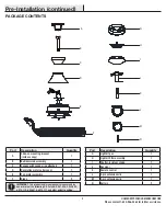
Part

Description

Quantity

A

Slide-on mounting bracket 
(inside canopy)

1

B

Ball/downrod assembly

1

C

Canopy with canopy ring attached

1

D

Decorative motor collar cover

1

E

Fan-motor assembly

1

F

Blade

3

Part

Description

Quantity

G

Light kit pan

1

H

Light kit fitter assembly

1

I

Shatter-resistant shade

1

J

Receiver

1

K

Remote control

1

L

3-pin extension wire

1

M

2-pin extension wire

1

N

Battery

2

IMPORTANT

: This product and/or components are governed by 

one or more of the following U.S. Patents: 5,947,436; 5,988,580; 

6,010,110; 6,046,416; 6,210,117 and other patents pending.

Pre-Installation (continued)

PACKAGE CONTENTS

A

B

C

F

D

H

G

E

L

J

K

M

I

N

Summary of Contents for 1005 469 518

Page 1: ...esigned to enhance your home Visit us online to see our full line of products available for your home improvement needs Thank you for choosing Home Decorators Collection Item 1005 469 518 Model 52060 UL Model 60 KEST USE AND CARE GUIDE KAYDEN 60 INCH CEILING FAN To view an instructional video on how to install this product 1 Go to www homedepot com and enter either the Item or Model number found i...

Page 2: ...bend the blade brackets also referred to as flanges during assembly or after installation Do not insert objects in the path of the blades WARNING To reduce the risk of fire or electric shock do not use this fan with any solid state speed control device WARNING Electrical diagrams are for reference only If you are using a light kit refer to the light kit instructions manual to make the electrical c...

Page 3: ...purchase All costs of removing and reinstalling the product are your responsibility Damage to any part such as by accident misuse improper installation or by affixing any accessories is not covered by this warranty Because of varying climatic conditions this warranty does not cover any changes in brass finish including rusting pitting corroding tarnishing or peeling Brass finishes of this type giv...

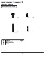
Page 4: ...scription Quantity AA Blade attachment screws 13 BB Plastic wire connecting nut 3 CC Hanger pin 1 DD Locking pin 1 Pre Installation continued HARDWARE INCLUDED NOTE Hardware not shown to actual size BB CC DD AA ...

Page 5: ... assembly 1 F Blade 3 Part Description Quantity G Light kit pan 1 H Light kit fitter assembly 1 I Shatter resistant shade 1 J Receiver 1 K Remote control 1 L 3 pin extension wire 1 M 2 pin extension wire 1 N Battery 2 IMPORTANT This product and or components are governed by one or more of the following U S Patents 5 947 436 5 988 580 6 010 110 6 046 416 6 210 117 and other patents pending Pre Inst...

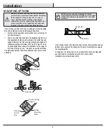
Page 6: ...et box and support structure must be securely mounted and capable of reliably supporting a minimum of 35 lbs 15 9 kg Use only UL listed outlet boxes marked Acceptable for fan support of 35 lbs 15 9 kg or less Do not use a plastic outlet box The illustrations below show three different ways to mount the outlet box If the canopy touches the downrod then remove the decorative canopy bottom cover and ...

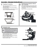
Page 7: ... canopy C is on top and insert the ball downrod B through the canopy C Route the wires exiting the top of the fan motor assembly E through the downrod as shown 2 3 1 NOTE The fan comes with 12 in lead wires for use with the provided 6 in ball downrod assembly B If you wish to use a longer downrod attach the 3 pin extension wire L and 2 pin extension wire M to the fan by connecting the molded adapt...

Page 8: ...ly Standard Ceiling Mount continued Assembling the fan Loosen but do not remove the setscrew KK on the collar PP on top of the fan motor assembly E Install the downrod B by inserting it into the motor collar PP and turning it clockwise until the holes at the bottom of the ball downrod assembly B align with the holes in the collar on top of the fan motor assembly E Carefully insert the hanger pin C...

Page 9: ...rtment to the 1 setting Confirm that the power to the fan is off at either the wall switch or breaker box Return power to the fan at the wall switch or breaker box Press and release the Learn button located in the remote s battery compartment within 30 seconds of turning on the power If pairing is successful the fan s light kit will flash and the blades will begin to spin Replace the battery cover...

Page 10: ...ing If you feel you do not have enough electrical wiring knowledge or experience contact a licensed electrician WARNING Each wire nut supplied with this fan is designed to accept up to one 12 gauge house wire and two wires from the fan If you have larger than 12 gauge house wiring or more than one house wire to connect to the fan wiring consult an electrician for the proper size wire nuts to use I...

Page 11: ...utlet box in the ceiling MM Green 1 2 3 4 ON DIP L M Mounting the fan motor assembly standard mount 7 WARNING When using the standard ball downrod mounting the tab in the ring at the bottom of the mounting bracket must rest in the groove of the hanger ball Failure to properly seat the tab in the groove could cause damage to the wiring NOTE The magnet is pre attached on the canopy bottom cover for ...

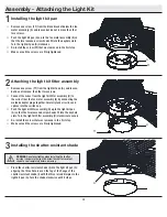
Page 12: ...alling the shatter resistant shade 3 Place the shatter resistant shade I into the light kit pan G aligning the three flat areas on the top of the flange of the shatter resistant shade I with the three raised dimples in the light kit pan G Turn the shade clockwise until it stops WARNING Do not overtighten when installing the shatter resistant shade into the light kit Allow the shatter resistant sha...

Page 13: ... wall cradle in the desired position and attach it to the wall using the included wall cradle screws Slide the screw cover plate back onto the wall cradle to conceal the screws Screw cover plate NOTE Screw wall anchors are included for extra support The included screws are designed to screw easily into the wall If you would like a more permanent or secure hold install the wall anchors prior to att...

Page 14: ...ress and release 3 times turns the fan speed to 3 Press and release 4 times turns the fan speed to 2 Press and release 5 times turns the fan speed to 1 Press and release 6 times turns the fan off NOTE The remote receiver includes a memory function that will return the fan to its last setting when turned on via the power button FAN REVERSE Press and release the fan reverse button to reverse the rot...

Page 15: ...otor fans Because of the fan s natural movement some connections may become loose Check the support connections brackets and blade attachments twice a year Make sure they are secure It is not necessary to remove the fan from the ceiling Clean your fan periodically to help maintain its new appearance over the years Do not use water when cleaning as this could damage the motor or the wood or possibl...

Page 16: ...blems missing parts Before returning to the store call Home Depot Customer Service 8 a m 7 p m EST Monday Friday 9 a m 6 p m EST Saturday 1 800 986 3460 HOMEDEPOT COM HOMEDECORATORS Retain this manual for future use ...

Page 17: ...r tu hogar Visítanos por Internet para ver nuestra línea completa de productos disponibles a fin de satisfacer tus necesidades de mejoras del hogar Gracias por haber elegido Home Decorators Collection Artículo núm 1005 469 518 Modelo Núm 52060 Modelo UL Núm 60 KEST GUÍA DE USO Y MANTENIMIENTO KAYDEN VENTILADOR DE TECHO 60 PLG Para ver un video instructivo sobre cómo instalar este producto 1 Ir a w...

Page 18: ...és de la instalación No insertes objetos en el trayecto de las aspas ADVERTENCIA Para reducir el riesgo de incendio o descarga eléctrica no uses este ventilador con ningún dispositivo de estado sólido para control de velocidad ADVERTENCIA Los diagramas eléctricos son sólo para referencia Si estás usando un kit de luces consulta su manual de instrucciones para hacer las conexiones eléctricas El uso...

Page 19: ...ido perforación corrosión manchas o descascaramiento Los acabados en latón de este tipo brindan la vida útil más larga al proteger contra las condiciones climáticas cambiantes Cierta oscilación es normal y no debe considerase un defecto Cualquier servicio prestado por personal no autorizado invalidará la garantía No hay ninguna otra garantía expresa Por este medio Interline queda exonerado de toda...

Page 20: ...Tornillos para ajustar aspas 13 BB Tuerca plástica de conexión de cables 3 CC Perno para colgar 1 DD Pasador de cierre 1 Pre instalación continuación SE INCLUYEN LOS HERRAJES NOTA Los herrajes no se muestran en tamaño real BB CC DD AA ...

Page 21: ...3 Pieza Descripción Cantidad G Carcasa del kit de luces 1 H Conjunto de instalación del kit de luces 1 I Pantalla resistente a impactos 1 J Receptor 1 K Control remoto 1 L Cable de extensión de 3 espigas 1 M Cable de extensión de 2 espigas 1 N Batería 2 IMPORTANTE Este producto o sus componentes están protegidos por una o más de las siguientes patentes de los EE UU 5 947 436 5 988 580 6 010 110 6 ...

Page 22: ...eben montarse de manera segura y ser capaces de soportar confiablemente un mínimo de 35 lb 15 9 kg Usa sólo cajas eléctricas aprobadas por UL y marcadas con aceptable para soporte de ventilador de 35 lb 15 9 kg o menos No uses una caja eléctrica de plástico Las ilustraciones más abajo muestran tres formas distintas de montar la caja eléctrica Si la cubierta toca el tubo descendente retira la cubie...

Page 23: ...ubo esfera B a través del dosel C Pasa los cables que salen de la parte superior del conjunto del motor del ventilador E a través del tubo bajante como se muestra 2 3 1 NOTA El ventilador viene con cables conductores de 12 pulgadas para usar con el conjunto de tubo bajante esfera de 6 pulgadas B Si deseas utilizar un tubo más largo conecta el cable de extensión de 3 espigas L y el cable de extensi...

Page 24: ...ador Afloja sin quitarlos los tornillos de fijación KK del collarín PP ubicados en la parte superior del conjunto del motor del ventilador E Instala el tubo bajante B insertándolo en el collar del motor PP y girándolo en el sentido de las agujas del reloj hasta que los orificios en la parte inferior del conjunto de esfera tubo B se alineen con los orificios en el collar en la parte superior del co...

Page 25: ...ción 1 Confirma que la alimentación del ventilador esté apagada en el interruptor de pared o en la caja de interruptores Regresa la energía al ventilador en el interruptor de pared o caja de interruptores Presiona y suelta el botón Learn Aprender ubicado en el compartimiento de las baterías del control remoto dentro de los 30 segundos de encender la alimentación Si el emparejamiento es exitoso el ...

Page 26: ...cientes conocimientos o experiencia de cableado eléctrico comunícate con un electricista con licencia ADVERTENCIA Cualquier cable no suministrado con este ventilador debe estar diseñado para aceptar un cable de vivienda de hasta calibre 12 y dos cables del ventilador Si tienes cableado doméstico que exceda del calibre 12 o más de un cable doméstico para conectar al cableado del ventilador consulta...

Page 27: ...IP L M Cómo montar el conjunto del motor del ventilador montaje estándar 7 ADVERTENCIA En el montaje estándar del conjunto esfera tubo bajante la pestaña en el aro de la parte inferior del soporte de montaje tiene que encajar en la ranura de la bola de soporte Si la pestaña no se asienta correctamente en la ranura se puede dañar el cableado NOTA El imán está preinstalado en la cubierta inferior de...

Page 28: ...sistente a impactos 3 Coloca la pantalla resistente a impactos I en la carcasa del kit de luces G alineando las tres áreas planas en el reborde superior de la pantalla resistente a impactos I con las tres muescas salientes de la carcasa del kit de luces G Gira la pantalla en el sentido de las manecillas del reloj hasta que se detenga ADVERTENCIA No aprietes demasiado cuando instales la pantalla re...

Page 29: ...ed en la posición deseada y fíjalo a la pared con los tornillos incluidos Desliza la placa de cubierta del tornillo nuevamente sobre el soporte para pared para ocultar los tornillos NOTA Se incluyen anclajes de pared de tornillo para soporte adicional Los tornillos incluidos están diseñados para atornillarse fácilmente en la pared Si deseas una sujeción más permanente o segura instala los anclajes...

Page 30: ... y suelta 2 veces para llevar la velocidad del ventilador a 4 Oprime y suelta 3 veces para llevar la velocidad del ventilador a 3 Oprime y suelta 4 veces para llevar la velocidad del ventilador a 2 Oprime y suelta 5 veces para llevar la velocidad del ventilador a 1 Oprime y suelta 6 veces para apagar el ventilador NOTA El receptor remoto incluye una función de memoria que devolverá el ventilador a...

Page 31: ...y permite que el ventilador funcione de manera mucho más silenciosa que los ventiladores de motor de CA estándar Debido al movimiento natural del ventilador algunas conexiones pueden aflojarse Revisa dos veces al año las conexiones del soporte los soportes y los accesorios de las aspas Comprueba que estén seguros No es necesario desmontar el ventilador del techo Limpia el ventilador con frecuencia...

Page 32: ...a tienda llama al Servicio al Cliente de Home Depot de lunes a viernes entre 8 00 a m y 7 00 p m Hora Estándar del Este y los sábados entre 9 00 a m y 6 00 p m Hora Estándar del Este 1 800 986 3460 HOMEDEPOT COM HOMEDECORATORS Conserva este manual para uso en el futuro ...

Reviews: