background image

18

Check the support connections, brackets, and blade attachments twice a year. Make sure they are secure. Because of the fan’s natural 
movement, some connections may become loose over time. It is not necessary to remove the fan from the ceiling.
Clean your fan periodically. Use only a soft brush or lint-free cloth to avoid scratching the finish. The plating is sealed with a lacquer to 
minimize discoloration or tarnishing.
(Optional) Apply a light coat of furniture polish to the wood blades.
(Optional) Cover small scratches with a light application of shoe polish.

Do

Use water when cleaning. Water could damage the motor, or the wood, or possibly cause an electrical shock.
Apply oil to your fan or motor. The motor has permanently-lubricated sealed ball bearings.

Do not

Care and Cleaning

Troubleshooting

Do not connect the fan with wall mounted variable speed control(s).

Make sure the frequency switches are set correctly.

Reset the transmitter by going through the transmitter “LEARNING PROCESS”.

This is normal start-up procedure for DC motor fans. The partial movement during start-up is the result

of the DC motor aligning the internal magnetic poles for proper motor operation. This design saves

electricity and allows the fan to operate much quieter than standard AC motor fans.

The fan wobbles.

Fan moves backwards and
forwards when turned on.

The remote control is 
not working.

Problem

Solution

Check the main and branch circuit fuses or breakers.

Check the line wire connections to the fan and switch wire connections in the switch housing.

Check to make sure the frequency switches from the remote control and receiver are set to the same

frequency.

Reset the transmitter by going through the transmitter “LEARNING PROCESS”.

Make sure all motor housing screws are snug.

Make sure the screws that attach the fan blade to the motor hub are tight.

Make sure the wire nut connections are not rattling against each other or the interior wall of the switch 

housing.

Allow a 24-hour "breaking-in" period. Most noises associated with a new fan disappear during this time.
If using the ceiling light kit, make sure the glassware is secured tightly.
Make sure there is a short distance from the ceiling to the canopy.  It should not touch the ceiling.
Make sure your ceiling box is secure and that rubber isolator pads are used between the mounting 

bracket and outlet box.

The fan will not start.

The fan sounds noisy.

Verify that all blades and blade bracket screws are secure (most fan wobble problems are caused by 
loose parts). Once the fan is properly installed, run the ceiling fan for 10 minutes to let the fan self-adjust. 

If wobble occurs after running the fan for 10 minutes, verify blade level using the following process:
- Select a point on the ceiling above the tip of one of the blades, then select any fan blade and measure 

from the center of the selected blade to the point on the ceiling. Rotate the fan until the next blade is 
positioned and repeat the measurement using the same point from the ceiling for every blade.  
Measurement deviations should be within 1/8 in. 

- If all deviations are less than 1/8 in. and the fan continues to wobble, please call Customer Service 

(

1-800-986-3460) to order a complimentary Blade Balancing Kit.

- If deviation is greater than 1/8 in. , please call Customer Service (

1-800-986-3460) to order complimentary 

replacements of your brackets.

Summary of Contents for 1006 971 678

Page 1: ...r full line of products available for your home improvement needs Thank you for choosing Home Decorators Collection THANK YOU Visual instruction of how to install this fan Visit www homedepot com and enter either the Item or Model number to find this fan and click the link of visual instruction in the product overview section Questions problems missing parts Before returning to the store call Home...

Page 2: ...ons spliced conductors should be turned upward and pushed carefully up into the outlet box The wires should be spread apart with the grounded conductor and the equipment grounding conductor on one side of the outlet box and ungrounded conductor on the other side of the outlet box All setscrews must be checked and retightened where necessary before installation Suitable for use with solid state spe...

Page 3: ...ing performed by unauthorized persons shall render the warranty invalid There is no other express warranty We hereby disclaim any and all warranties including but not limited to those of merchantability and fitness for a particular purpose to the extent permitted by law The duration of any implied warranty which cannot be disclaimed is limited to the time period as specified in the express warrant...

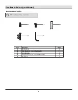
Page 4: ...HARDWARE INCLUDED Pre Installation continued AA BB CC DD EE Plastic wire nut Blade attachment screw with lock washer 1 5V AAA battery Safety cable screw lock washer and flat washer Hex wrench Part Description 3 19 2 1 1 Quantity AA DD EE BB CC ...

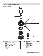
Page 5: ...ht cover Remote control Quantity 6 6 1 1 1 1 Part A B C D E F G Quantity 1 1 1 1 1 1 6 Description Mounting bracket preassembled Canopy Canopy bottom cover preassembled Hanger ball downrod assembly Coupling cover Fan motor assembly Blade arm H I J K L F M G C D E B A Please contact 1 800 986 3460 for further assistance HOMEDEPOT COM HOMEDECORATORS 5 ...

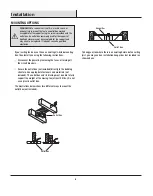
Page 6: ...box The illustrations below show two different ways to mount the outlet box not included To hang your fan where there is an existing fixture but no ceiling joist you may need an installation hanger bar not included as shown above Outlet Box Outlet Box Hanger Bar Outlet Box WARNING To reduce the risk of fire electric shock or personal injury mount the fan to an outlet box marked acceptable for fan ...

Page 7: ...rench EE provided Make sure the cross pin LL is in the correct position the setscrews JJ are tightened and wires are not twisted Preparing the motor 2 Remove the cotter pin GG and clevis pin HH and loosen the two collar setscrews II from the motor collar Loosen two setscrews JJ located in the hanger ball KK by using the hex wrench EE provided Lower the hanger ball KK and remove the cross pin LL Re...

Page 8: ...rely tighten the two mounting screws WARNING The tab in the ring must rest in the groove of the hanger ball downrod assembly D Failure to properly seat the tab in the groove could cause damage to the wiring Hanging the fan to the mounting bracket 5 Remove two screws OO from two upper sides of hanger ball KK Carefully lift the fan motor assembly F up to the mounting bracket A and seat the hanger ba...

Page 9: ... no loose strands or connections Make wire connections as follows using the wire nuts AA From Fan To Outlet Box Black Wire Black Wire Hot White Wire White Wire Neutral Green Wires Green or Bare Wire Ground There are two green grounding leads one from the mounting bracket A and one from the hanger ball downrod assembly D Turn the wire nut connections upward spreading them apart so the green ground ...

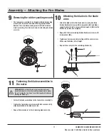
Page 10: ...ign the circular hole on the canopy B with the remaining hole on the mounting bracket A secure the canopy mounting screw FF previously removed in the hole and tighten the two canopy mounting screws FF NOTE Adjust the canopy mounting screws FF as necessary until the canopy B and canopy bottom cover C are snug Attaching the canopy bottom cover 8 Attach the canopy bottom cover C to the canopy mountin...

Page 11: ...ssembly F is shipped with rubber packing mounts PP to prevent movement during transportation Remove the six rubber packing mounts PP from the fan motor assembly F and discard prior to attaching the blade arms G Please contact 1 800 986 3460 for further assistance HOMEDEPOT COM HOMEDECORATORS 11 G H F F PP QQ WARNING To reduce the risk of personal injury do not bend the blade arms G while installin...

Page 12: ...cient to prevent electric shock Remove one of the three light kit mounting screws TT from the light kit mounting plate J and loosen the other two screws TT Do not remove While holding the 24W LED light kit K under the fan motor assembly F make the 2 pin wire connections White to white Blue to black Place the key holes in the 24W LED light kit K over the two mounting screws TT previously loosened f...

Page 13: ...tery compartment to the 1 position Turn the fan s AC power ON Within 60 seconds of turning AC power on press and release the LEARN button located in the remote s battery compartment to enter the learning function Once the fan has detected the remote controls s frequency the down light of your fan if applicable will blink and the fan blades will start to spin The fan will now accept commands from t...

Page 14: ...RN button located in the remote s battery compartment and your fan will restore to the original setting and dismiss the other remotes M APRENDER LEARN LEARN Warm weather Forward Dimmer Comfort BreezeTM LED bar Scale indicating fan speed Timer Power on off Light on off Cool weather Reverse Fan on and decreases fan speed Fan on and increases fan speed Correlated Color Temperature CCT changing The an...

Page 15: ...ease will cause the LED bar to dim slightly more until the fan has reached the minimum speed setting At that time the LED bar will be approximately 25 illuminated Pressing and holding the button will decrease the fan speed automatically through the speed settings and the reductions will be denoted on the LED bar When the LED bar is 25 illuminated the fan has reached the minimum speed setting Press...

Page 16: ...ush and release the button to cycle through the three color temperature options Option 1 3000K Soft White Option 2 4000K Bright White Option 3 5000K Daylight 8 Correlated Color Temperature CCT changing 5 Fan reverse button Must be pushed when the fan is in operation Warm weather LED bar will illuminate and the lights will flow from high to low Cool weather LED bar will illuminate and the lights wi...

Page 17: ...arm weather Counterclockwise Direction A downward air flow creates a cooling effect This allows you to set your air conditioner on a warmer setting without affecting your comfort Cool weather Clockwise Direction An upward air flow moves warm air off the ceiling This allows you to set your heating unit on a cooler setting without affecting your comfort NOTE The fan reverse buttons must be pressed w...

Page 18: ...tches from the remote control and receiver are set to the same frequency Reset the transmitter by going through the transmitter LEARNING PROCESS Make sure all motor housing screws are snug Make sure the screws that attach the fan blade to the motor hub are tight Make sure the wire nut connections are not rattling against each other or the interior wall of the switch housing Allow a 24 hour breakin...

Page 19: ... not installed and used in accordance with the instructions may cause harmful interference to radio communications However there is no guarantee that interference will not occur in a particular installation If this equipment does cause harmful interference to radio or television reception which can be determined by turning the equipment off and on the user is encouraged to try to correct the inter...

Reviews: