


6
Installation
MOUNTING OPTIONS
WARNING:
To reduce the risk of fire, electric shock,
or personal injury, mount the fan to an outlet box
marked “Acceptable for fan support of 35 lbs. (15.9
kg) or less” and use the screws provided with the
outlet box. An outlet box commonly used for the
support of lighting fixtures may not be acceptable for
fan support and may need to be replaced. If in doubt,
consult a qualified electrician.
If your ceiling fan does not have an existing UL-listed mounting
box, then install one using the following instructions:
□
Disconnect the power by removing the fuses or turning off
the circuit breakers.
□
Secure the outlet box directly to the building structure.
Use the appropriate fasteners and materials. The outlet box
and its bracing must be able to fully support the weight
of the moving fan (at least 35 lbs.). Do not use a plastic
outlet box.
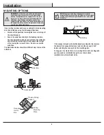
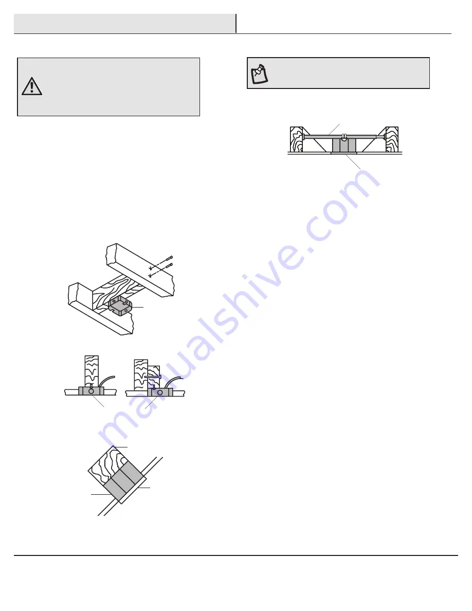
The illustrations below show three different ways to mount the
outlet box.
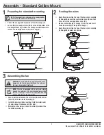
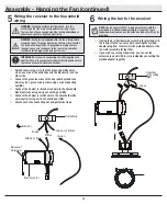
If the canopy (C) touches the ball/downrod assembly (B), then remove
the decorative canopy bottom cover and turn the canopy (C) 180°
before attaching the canopy (C) to the mounting plate.
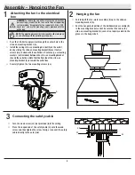
To hang your fan where there is an existing fixture but no ceiling joist,
you may need an installation hanger bar as shown above
(available at any Home Depot store).
NOTE:
You may need a longer downrod to maintain
proper blade clearance when installing on a steep, sloped
ceiling. The maximum angle allowable is 30° away from
horizontal.
Outlet Box
Outlet Box
Recessed
Outlet
Box
Provide Strong
Support
Ceiling
Mounting
Plate
Outlet Box
Hanger Bar


