background image

13

HOMEDEPOT.COM/HOMEDECORATORS

Please contact 1-800-986-3460 for further assistance.

YY

Operating Your Fan and Remote Control

Remote Control - Your fan is equipped with a remote control to operate
the speed and lights of your new ceiling fan. 

Speed setting for warm or cool weather depends on factors such as 
the room size, ceiling height, number of fans and so on.

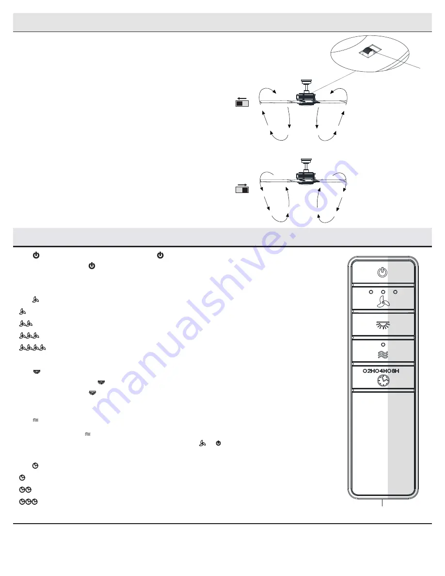
The fan is shipped from the factory with the reversing switch (YY) 
positioned to circulate air downward. If airflow is desired in the 
opposite direction, turn your fan off and wait for the blades to stop 
turning, then slide the reversing switch (located on the top of the 
motor housing) to the opposite position, and turn the fan on again. The 
fan blades will turn in the opposite direction and reverse airflow.

Warm weather

 - (Forward) A downward airflow creates a cooling effect.

This allows you to set your air conditioner on a higher setting without
affecting your comfort.

Cool weather

 - (Reverse) An upward airflow moves warm air off of the

ceiling. This allows you to set your heating unit on a lower setting
without affecting your comfort.

A. Warm weather

B. Cool weather

1.  

 Power ON/OFF.

 - Press and release the


button to turn the fan and light on or off.


Press and hold the


button for 5 seconds to use the “walk away time delay”; this will active the light 

for 30 seconds (the light will be activated at 50% brightness).

2. 

 Fan Speed - 

LEDs on the fan speed button will illuminate to the corresponding speed.

 - Press and release 1 time - turns the fan on high speed.

 - Press and release 2 times - turns the fan on medium speed.

 - Press and release 3 times - turns the fan on low speed.

 - Press and release 4 times - turns the fan off.

3.  

 Light ON/OFF 


Press and release the 

 button to turn the light on or off.


Press and hold the 

 button to activate the dimmer function (as long as you have NOT previously set 

O/D dip switch in your remote to the “ON” position).

4. 

 Comfort Breeze

TM 


Press and release     button to enable Comfort Breeze

TM

; this will change your fan speed randomly, 

simulating a relaxing breeze. To cancel this feature press   or  .

5. 

 Timer 


 - While the fan is on press 1 time - turns on a 2 hour run timer.

 - While the fan is on press 2 times - turns on a 4 hour run timer.

 - While the fan is on press 3 times - turns on an 8 hour run timer.

Operating Your Fan and Remote Control

N

Summary of Contents for 56082

Page 1: ... quality products designed to enhance your home Visit us online to see our full line of products available for your home improvement needs Thank you for choosing Home Decorators Collection Item XXXX XXX XXX Model 56082 UL Model 52 VAGN WINDLOW 52 INCH CEILING FAN To view an instructional video on how to install this product 1 Go to www homedepot com and enter either the Item or Model number found ...

Page 2: ... spliced conductors should be turned upward and pushed carefully up into the outlet box The wires should be spread apart with the grounded conductor and the equipment grounding conductor on one side of the outlet box 10 All setscrews must be checked and retightened where necessary before installation WARNING To reduce the risk of personal injury do not bend the blade brackets also referred to as f...

Page 3: ...nder the warranty invalid There is no other express warranty Home Decorators Collection hereby disclaims any and all warranties including but not limited to those of merchantability and fitness for a particular purpose to the extent permitted by law The duration of any implied warranty which cannot be disclaimed is limited to the time period as specified in the express warranty Some states do not ...

Page 4: ... Part Description Quantity AA Blade attachment screws 21 BB Blade bracket screw 11 CC Plastic wire connector 3 Pre Installation continued HARDWARE INCLUDED NOTE Hardware not shown to actual size AA CC BB ...

Page 5: ... arm 5 Part Description Quantity H Blade arm medallion 10 I Light kit pan 1 J Light kit fitter assembly 1 K Shatter resistant bowl 1 L Receiver 1 M Remote control battery included 1 N Extension lead wire 1 IMPORTANT This product and or components are governed by one or more of the following U S Patents 5 947 436 5 988 580 6 010 110 6 046 416 6 210 117 and other patents pending Pre Installation con...

Page 6: ...Use the appropriate fasteners and materials The outlet box and its bracing must be able to fully support the weight of the moving fan at least 35 lbs Do not use a plastic outlet box The illustrations below show three different ways to mount the outlet box If the canopy C touches the ball downrod assembly B then remove the decorative canopy bottom cover and turn the canopy C 180 before attaching th...

Page 7: ...locks Loosen the two canopy screws DD located in the bottom of the mounting bracket A and turn the canopy counterclockwise to remove the mounting bracket A from canopy C Assembling the fan Loosen but do not remove the setscrew GG on the collar FF on top of the fan motor assembly E Install the downrod B by inserting it into the motor collar FF and turning it clockwise until it is tight Re tighten t...

Page 8: ... outlet box Securely tighten the two mounting screws JJ Carefully lift the fan motor assembly E up to the slide on mounting bracket A Seat the hanger ball portion of the ball downrod assembly B in the mounting bracket socket Ensure that the tab on the slide on mounting bracket A socket is properly seated in the groove in the hanger ball 1 2 WARNING To reduce the risk of fire electric shock or othe...

Page 9: ... silicone rubber stopper OO into the hole on the receiver L to cover the dip switches M L ZZ 1 2 3 4 ON D O 1 2 3 4 ON DIP 1 2 3 4 ON D O 1 2 3 4 ON OO NOTE The battery will weaken with age and should be replaced before leaking takes place as this will damage the hand unit Dispose of used battery properly and keep the battery out of the reach of children 4 Installing the receiver Position the hous...

Page 10: ...cting nut AA Connect the receiver L white wire to the household white wire neutral using a wire connecting nut AA Secure each wire connecting nut using electrical tape WARNING To avoid possible electrical shock turn the electricity off at the main fuse box before wiring If you feel you do not have enough electrical wiring knowledge or experience contact a licensed electrician Wiring the fan to the...

Page 11: ...e canopy C and turn clockwise until the alignment post KK engage to the round hole and the screws CC engage to the key slots Firmly tighten the two mounting screws DD Install the decorative bottom cover EE by aligning the cover slots with screws in the bottom of the canopy C Rotate the bottom cover EE clockwise to lock in place 7 WARNING When using the standard ball downrod mounting the tab in the...

Page 12: ...supply circuit to the fan before installing the light kit pan Installing the shatter resistant bowl 3 Place the shatter resistant bowl K into the light kit pan I aligning the three flat areas on the top flange of the shatter resistant bowl K with the three raised dimples in the light kit pan Turn the shatter resistant bowl K clockwise until it stops CAUTION Make sure the power is off before attach...

Page 13: ...t on a lower setting without affecting your comfort A Warm weather B Cool weather 1 Power ON OFF Press and release the button to turn the fan and light on or off Press and hold the button for 5 seconds to use the walk away time delay this will active the light for 30 seconds the light will be activated at 50 brightness 2 Fan Speed LEDs on the fan speed button will illuminate to the corresponding s...

Page 14: ... blade arm screws are secure Most fan wobble problems are caused when blade levels are unequal Check this level by selecting a point on the ceiling above the tip of one of the blades Measure from a point on the center of each blade to the point on the ceiling Rotate the fan until the next blade is positioned for measurement Repeat for each blade Any measure ment deviation should be within 1 8 Run ...

Page 15: ...ular installation If this equipment does cause harmful interference to radio or television reception which can be determined by turning the equipment off and on the user is encouraged to try to correct the interference by one or more of the following measures Reorient or relocate the receiving antenna Increase the separation between the equipment and receiver Connect the equipment into an outlet o...

Reviews: