

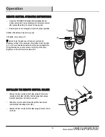

Pre-Installation (continued)
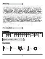
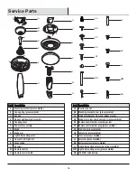
HARDWARE INCLUDED
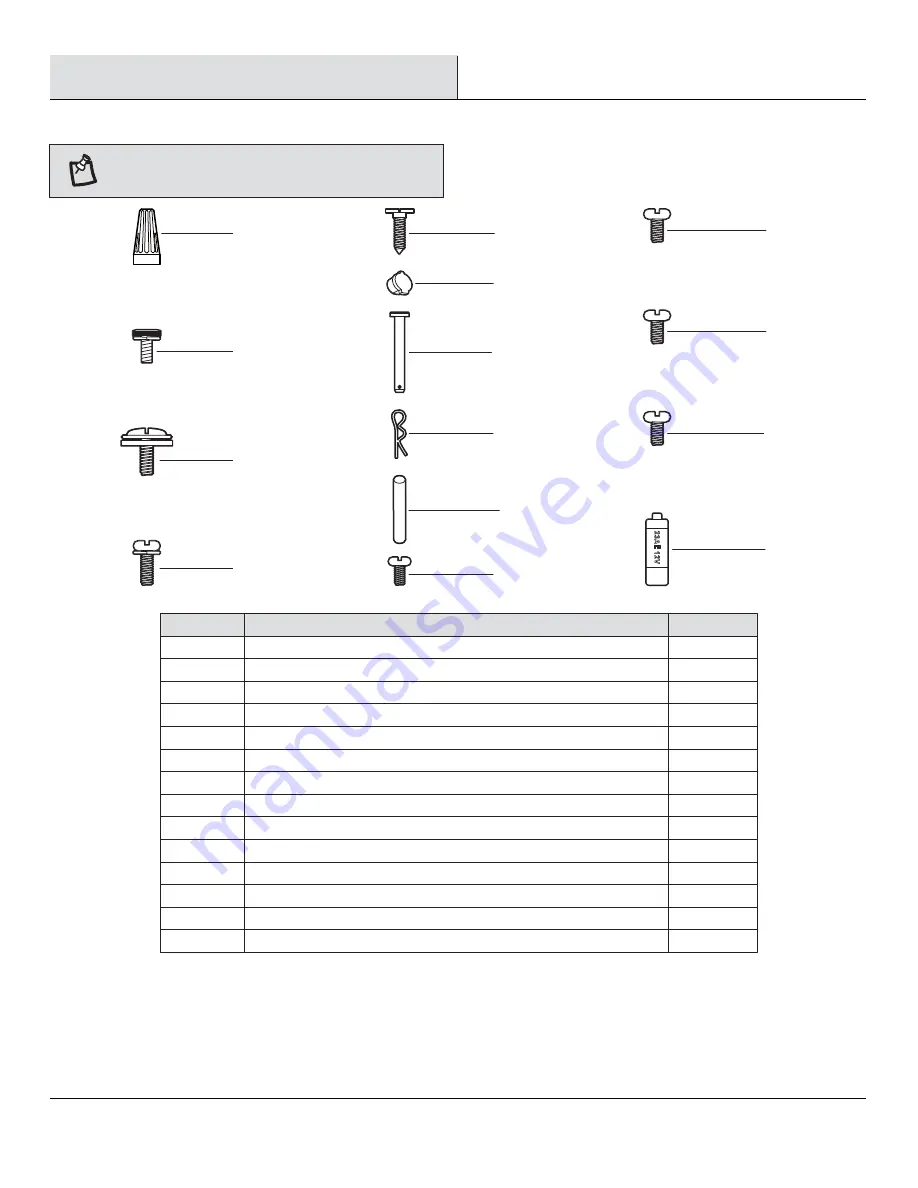
HARDWARE INCLUDED
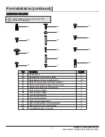
NOTE:
Hardware shown to actual size unless noted
otherwise in the table below.
AA
BB
CC
DD
EE
FF
GG
HH
II
JJ
KK
LL
MM
NN
Plastic wire nut
Mounting bracket screw (preassembled)
Blade attachment screw and rubber washer
Blade arm screw and lock washer (preassembled)
Remote control holder mounting screw (not to scale)
Remote control holder plug (preassembled)
Clevis pin (preassembled)
Cotter pin (preassembled)
Cross pin (preassembled)
Setscrew (preassembled)
Collar setscrew (preassembled)
Light kit mounting plate screw (preassembled)
Light kit mounting screw (preassembled)
12V MN21/A23 battery (not to scale)
Part
Part
Description
Description
9
2
13
9
2
2
1
1
1
1
2
3
3
1
Quantity
Quantity
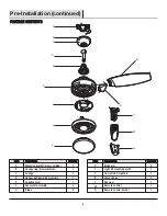
LL
KK
MM
NN
EE
FF
GG
HH
II
JJ
AA
BB
CC
DD
5
HOMEDEPOT.COM/HOMEDECORATORS
Please contact 1-800-986-3460 for further assistance.


