background image

11

HOMEDEPOT.COM/HOMEDECORATORS

Please contact 1-800-986-3460 for further assistance.

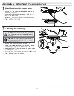
Attaching the fan blades

9


Attach blade (G) to blade bracket (J) using the decorative nuts 
(CC) and blade attachment screws (AA) provided. Insert a blade 
attachment screw (AA) through a hole in the blade (G) and 
blade bracket (J) into a decorative nut (CC). Repeat for the two 
remaining holes in the blade (G).


Tighten each blade attachment screw (AA) securely.


Repeat these steps for the remaining blades.

Assembly - Hanging the Fan (continued)

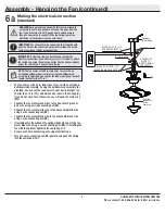
Wrapping the extra wire


Gently wrap the excess wire around the mounting bracket.


Secure with electrical tape.

7

NOTE:

 Follow this step ONLY if you did not cut the extra length off 

from the wires coming from the ceiling fan.

J

AA

G

CC

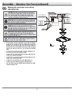
Mounting the fan


Align the locking slots of the ceiling canopy (C) with the two 
screws (HH) in the slide-on mounting bracket (A). Push up to en-
gage the slots, and turn clockwise to lock the canopy (C) in place.


Firmly tighten the two mounting screws.


Install the two mounting screws (saved from Assembly Step 1 
“Preparing for mounting”) into the holes in the canopy (C) and 
tighten firmly.


Install the decorative canopy ring (L) by aligning the ring’s slots 
with the screws in the canopy (C). Rotate the canopy ring coun-
terclockwise to lock it in place.

8

WARNING:

 When using the standard ball/downrod mounting, the 

tab in the ring at the bottom of the mounting bracket must rest in 

the groove of the hanger ball. Failure to properly seat the tab in 

the groove could cause damage to the wiring.

WARNING:

 The locking slots of  ceiling canopy are provided only 

as an aid to mounting. Do not leave the fan assembly unattached 

until all four canopy screws are engaged and firmly tightened.

A

C

L

HH

Summary of Contents for 987 787

Page 1: ...trust and confidence you have placed in Home Decorators Collection through the purchase of this ceiling fan We strive to continually create quality products designed to enhance your home Visit us onli...

Page 2: ...assembly 9 This product is suitable for use in wet locations when installed in a GFCI protected branch circuit 10 After making electrical connections spliced conductors should be turned upward and pu...

Page 3: ...no other express warranty Home Decorators Collection hereby disclaims any and all warranties including but not limited to those of merchantability and fitness for a particular purpose to the extent p...

Page 4: ...Part Description Quantity AA Blade attachment screws 15 BB Plastic wire connecting nut 3 CC Decorative nut 15 HARDWARE INCLUDED NOTE Hardware not shown to actual size AA BB CC Pre installation continu...

Page 5: ...g attached 1 D Fan motor assembly 1 E Switch cup 1 Part Description Quantity F Decorative motor collar cover 1 G Blade 5 H Switch cup adaptor 1 I Wall control 1 IMPORTANT This product and or component...

Page 6: ...opriate fasteners and materials The outlet box and its bracing must be able to fully support the weight of the moving fan at least 50 lbs 22 7 kg Do not use a plastic outlet box The illustrations belo...

Page 7: ...and through the canopy ring L Make sure the slot openings are on top and route the wires through the canopy C and then through the ball downrod assembly B 2 3 1 C A SS L HH C L B F D Loosen but do no...

Page 8: ...box OO Note that the flat side of the mounting bracket A is toward the outlet box OO Securely tighten the two mounting screws TT Carefully lift the fan motor assembly D up to the slide on mounting bra...

Page 9: ...a wire connecting nut BB Connect the fan motor white wire to the household white wire using a wire connecting nut BB Connect the fan motor black wire to the household black wire using a wire connectin...

Page 10: ...usehold white wire using a wire connecting nut BB Connect the fan motor black wire to the household black wire using a wire connecting nut BB Connect the fan motor blue wire to the light switch wire S...

Page 11: ...Align the locking slots of the ceiling canopy C with the two screws HH in the slide on mounting bracket A Push up to en gage the slots and turn clockwise to lock the canopy C in place Firmly tighten...

Page 12: ...he switch cup E Connect the molded adaptor plug in the switch cup with the molded adaptor plug of the fan motor assembly D Align the holes on the switch cup E with the screws on the switch cup adaptor...

Page 13: ...wire through the lockwasher HH and hex nut II Tighten them securely Connect the blue wires exiting the switch cup E with the black wire from the top of the light kit fitter assembly Connect the white...

Page 14: ...ot sufficient to prevent shock All wiring must be in accordance with National and Local codes and the ceiling fan must be properly grounded as a precaution against possible electrical shock Disconnect...

Page 15: ...unequal Check this level by selecting a point on the ceiling above the tip of one of the blades Measure from a point on the center of the blade to the point on the ceiling Rotate the fan until the ne...

Page 16: ...estions problems missing parts Before returning to the store call Home Depot Customer Service 8 a m 6 p m EST Monday Friday 1 800 986 3460 HOMEDEPOT COM HOMEDECORATORS Retain this manual for future us...

Reviews: