
Part
Part
A
B
C
D
E
F
G
H
I
J
K
L
M
N
Description
Description
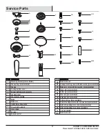
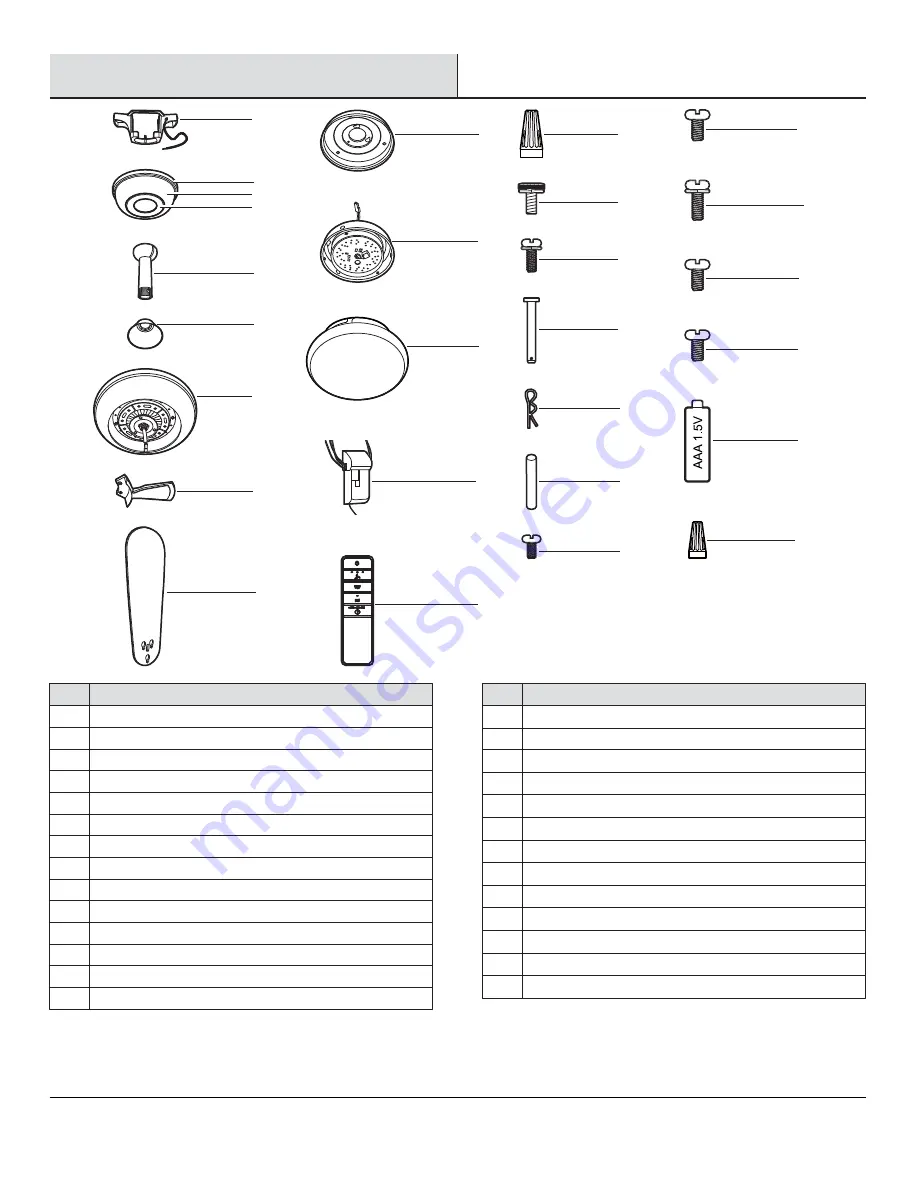
Mounting bracket (preassembled)
Canopy ring (preassembled)
Canopy
Canopy bottom cover
Hanger ball/downrod assembly
Coupling cover
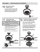
Fan motor assembly
Blade
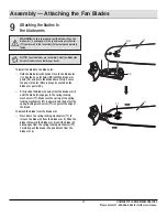
Blade arm
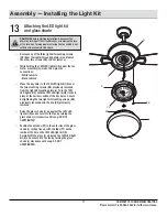
Light kit mounting plate
14 watt LED Light kit
Glass shade
Receiver
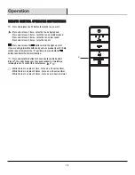
Remote control
Part
AA
BB
CC
DD
EE
FF
GG
HH
II
JJ
KK
LL
MM
Description
Description
Plastic wire nut
Canopy mounting screw with lock washer (preassembled)
Blade arm screw with lock washer (preassembled)
Clevis pin (preassembled)
Cotter pin (preassembled)
Cross pin (preassembled)
Setscrew (preassembled)
Collar setscrew (preassembled)
Collar mounting screw with lock washer (preassembled)
Light kit mounting plate screw (preassembled)
Light kit mounting screw (preassembled)
1.5V AAA battery
Plastic wire nut
Service Parts
21
HOMEDEPOT.COM/HOMEDECORATORS
Please contact 1-800-986-3460 for further assistance.
A
K
L
M
N
E
F
G
H
I
AA
BB
CC
DD
EE
FF
GG
JJ
II
HH
KK
LL
MM
B
C
D
J


