background image

2

Tabla de contenido .............................................................. 2

Información de seguridad................................................... 2

Garantía ................................................................................ 3

Preinstalación ...................................................................... 3

Instalación............................................................................ 6

Ensamblaje........................................................................... 7

Funcionamiento ................................................................. 14

Mantenimiento y limpieza................................................. 17

Solución de problemas ..................................................... 17

1.

Para disminuir el riesgo de descarga eléctrica, asegúrate de 
cortar la electricidad del cortacircuitos o la caja de fusibles antes 
de comenzar.

2.

Todo el cableado debe cumplir con el Código Nacional de 
Electricidad ANSI/NFPA 70-1999 y con los códigos locales 
de electricidad. La instalación eléctrica debe hacerse por un 
electricista certificado y calificado. 

3.

La caja eléctrica y la estructura de soporte tienen que montarse 
de forma segura y ser capaces de sostener con fiabilidad un 
mínimo de 35 lb (15.9 kg). Usa solamente cajas eléctricas 
aprobadas por UL marcadas como “apropiada para sostener 
ventiladores de 35 lb (15.9 kg) o menos”.

4.

El ventilador tiene que montarse con un mínimo de 2.13 m de 
separación entre el borde trasero de las aspas y el piso.

5.

No coloques objetos en la trayectoria de las aspas.

6.

Para evitar lesiones físicas o daños al ventilador y otros artículos, 
ten cuidado al limpiarlo o al trabajar cerca de él.

7.

Después de concluir las conexiones eléctricas, debes voltear los 
conductores empalmados hacia arriba y meterlos con cuidado en 
la caja eléctrica. Los cables deben estar separados con el cable 
a tierra y el conductor a tierra del equipo a un lado de la caja 
eléctrica.

8.

Todos los tornillos colocados tienen que verificarse y ajustarse 
donde sea necesario antes de la instalación.

(+=,9;,5*0(!

 Para reducir el riesgo de lesiones personales,

no dobles los soportes de las aspas (también llamados “bridas”) 
durante el ensamblaje ni después de la instalación.
No coloques objetos en la trayectoria de las aspas.

(+=,9;,5*0(!

 Al efecto de disminuir el riesgo de incendio

o descarga eléctrica, no utilices este ventilador con ningún 
dispositivo de estado sólido para control de velocidad.

(+=,9;,5*0(!

 Los diagramas eléctricos son tan solo para 

referencia. Si usas un kit de luces, consulta el manual
de instrucciones del kit de luces para hacer las conexiones
eléctricas. Cualquier juego de luces opcional deberá estar 
aprobado por UL y marcado como adecuado para usar con 
este ventilador.

(+=,9;,5*0(!

 Para evitar una posible descarga eléctrica, 

corta la energía eléctrica en la caja principal de fusibles 
antes del cableado. Si crees que no tienes suficiente 
experiencia o conocimientos sobre cableado eléctrico, 
contrata a un electricista certificado.

Información de seguridad

Tabla de contenido

79,*(<*0Ô5!

 Para reducir el riesgo de lesiones personales,

usa solo los tornillos incluidos con la caja eléctrica.

(+=,9;,5*0(!

 Para reducir el riesgo de incendio, descarga

eléctrica o lesiones personales, instala solo en una caja 
eléctrica clasificada como “apropiada para sostener 
ventiladores de 35 lb (15.9 Kg) o menos” y usa los tornillos 
que vienen con ésta.

LEE Y GUARDA ESTAS INSTRUCCIONES.

(+=,9;,5*0(!

 Para reducir el riesgo de incendio o 

descarga eléctrica este ventilador sólo debe usarse con 
un control de velocidad (parte núm. MR101Z) fabricado 
por Satellite Electronic Co., LTD.

79,*(<*0Ô5!

 NO usar este ventilador con control

de pared o interruptor regulador de intensidad.
Usar un interruptor o control de pared con regulador
de intensidad dañará este ventilador.

79,*(<*0Ô5!

 Los cambios o modificaciones sin previa 

aprobación expresa de la parte responsable de su 
cumplimiento podrían anular el derecho del usuario a 
operar el equipo.

Este equipo ha sido comprobado y se determinó que cumple con los límites establecidos para un dispositivo digital Clase B, de acuerdo con la Parte 15 de las 
Normas de la FCC. Estos límites fueron establecidos para ofrecer protección razonable contra la interferencia dañina durante uso residencial.
Este equipo genera, usa y puede irradiar energía de radiofrecuencia; si no se instala y usa de acuerdo con las instrucciones, puede causar interferencia dañina 
a comunicaciones radiales. Sin embargo, no hay garantía de que no ocurrirá interferencia en una instalación particular. Si este equipo causa interferencia que 
perjudica la recepción de radio o televisión, lo cual puede determinarse encendiendo y apagando el equipo, se recomienda al usuario que trate de corregir la 
interferencia con una o más de las siguientes medidas:
– Reorientar o reubicar la antena receptora.
– Incrementar la distancia entre los equipos y el receptor.
– Conectar el equipo a un tomacorriente en un circuito distinto al que el receptor está conectado.
– Consultar al distribuidor o algún técnico de radio/TV con experiencia.
PRECAUCIÓN:
Los cambios o modificaciones sin aprobación expresa del responsable de este dispositivo podrían anular el derecho del usuario a operar el equipo.
Este dispositivo cumple con la Parte 15 de las Normas de FCC. Su operación está sujeta a las dos condiciones siguientes: (1) Este dispositivo no debe causar 
interferencia dañina, y (2) tiene que aceptar cualquier interferencia recibida, incluyendo aquella que pudiera afectar su funcionamiento.      

Summary of Contents for EASTWIND 43260

Page 1: ...ciate the trust and confidence you have placed in Home Decorators Collection through the purchase of this ceiling fan We strive to continually create quality products designed to enhance your home Visit us online to see our full line of products available for your home improvement needs Thank you for choosing Home Decorators Collection Item 1001 XXX XXX Model 43260 UL Model 52 EWD USE AND CARE GUI...

Page 2: ...ensed electrician Safety Information Table of Contents 065 To reduce the risk of personal injury use only the screws provided with the outlet box 9505 To reduce the risk of fire electric shock or personal injury mount to outlet box marked Acceptable for fan support of 35 lbs 15 9 kg or less and use screws provided with the outlet box READ AND SAVE THESE INSTRUCTIONS 9505 To reduce the risk of fire...

Page 3: ...thorized persons shall render the warranty invalid There is no other express warranty Home Decorators Collection hereby disclaims any and all warranties including but not limited to those of merchantability and fitness for a particular purpose to the extent permitted by law The duration of any implied warranty which cannot be disclaimed is limited to the time period as specified in the express war...

Page 4: ...ws 13 BB Plastic wire connecting nut 3 Pre Installation continued HARDWARE INCLUDED NOTE Hardware not shown to actual size AA BB TOOLS REQUIRED Phillips screwdriver Flat blade screwdriver Adjustable wrench Electrical tape Wire cutter Stripper Step ladder ...

Page 5: ...over 1 E Fan motor assembly 1 Part Description Quantity F Blade 3 G Light kit pan 1 H Light kit fitter assembly LED included 1 I Glass bowl 1 J Receiver 1 K Remote control battery included 1 IMPORTANT This product and or components are governed by one or more of the following U S Patents 5 947 436 5 988 580 6 010 110 6 046 416 6 210 117 and other patents pending Pre Installation continued PACKAGE ...

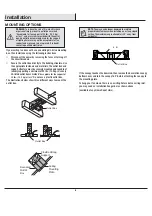
Page 6: ... outlet box and support structure must be securely mounted and capable of reliably supporting a minimum of 35 lbs 15 9 kg Use only UL listed outlet boxes marked Acceptable for fan support of 35 lbs 15 9 kg or less Do not use a plastic outlet box The illustrations below show three different ways to mount the outlet box If the canopy touches the downrod then remove the decorative canopy bottom cover...

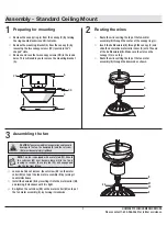
Page 7: ...or collar cover D onto the end of the ball downrod B Make sure the slots on the canopy C are on top Ƒ Route the wires exiting the top of the fan motor assembly E through the downrod as shown 2 3 1 C A L DD CC C D E L B M E B FF EE Ƒ Loosen but do not remove the setscrew EE on the motor collar M on top of the fan motor assembly E by turning it counterclockwise Ƒ Install the downrod B by inserting i...

Page 8: ...15 9 kg or less and use screws provided with the outlet box A II II 56 The mounting bracket A is designed to slide into place on an outlet box with the outlet box screws II installed A B E C D 3 56 The frequencies on your receiver and hand unit have been preset at the factory Before installing the receiver make sure the dip switches on the receiver and hand unit are set to the same frequency The d...

Page 9: ... conjunction with any variable wall control Incorrect wire connection can damage this receiver 065 If other fan wires are a different color have this unit installed by a licensed electrician 065 Do not install the receiver in a damp location or immerse in water For indoor use only Do not pull on or cut the receiver leads shorter Do not drop or bump the unit B C AAA BBB A J WINK antenna mount to ce...

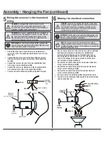
Page 10: ...the lead wires to your desired length no shorter than 12 in 5 Wiring the receiver to the household wiring 04769 5 Use the wire connecting nuts BB supplied with your fan Secure the connectors with electrical tape and ensure there are no loose strands or connections 9505 Each wire not supplied with this fan is designed to accept up to one 12 gauge house wire and two wires from the fan If you have la...

Page 11: ...the standard ball downrod mounting the tab in the ring at the bottom of the mounting bracket must rest in the groove of the hanger ball Failure to properly seat the tab in the groove could cause damage to the wiring Assembly Hanging the Fan continued 8 Wrapping the extra wire Ƒ Gently wrap the excess wire around the mounting bracket under the receiver Ƒ Secure with electrical tape 7 56 Follow this...

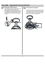
Page 12: ... sure all the screws are firmly tightened E AA F Assembly Hanging the Fan continued 9 Mounting the WINK antenna Ƒ Before adhering the antenna to the ceiling make sure the section of ceiling is clean and free of dirt or dust Ƒ Remove the protective strip from the double stick tape on the T shaped antenna and stick the antenna to the ceiling Ƒ Secure the antenna to the ceiling by inserting the wood ...

Page 13: ...ect the blue wire exiting the bottom of the fan motor assembly E with the black wire from the top of the light kit fitter assembly H Ƒ Connect the white wire exiting the bottom of the fan motor assembly E with the white wire from the top of the light kit fitter assembly H Ƒ Push the light kit fitter assembly H up to the light kit pan so that the two loosened screw heads fit into the keyhole slots ...

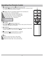
Page 14: ...elease 5 times turns the fan off 3 Light ON OFF Ƒ Press and release the button to turn the light on or off Ƒ Press and hold the button to activate the dimmer function as long as you have NOT previously set O D dip switch in your remote to the ON position 4 Comfort BreezeTM Ƒ Press and release the button to enable Comfort BreezeTM this will change your fan speed randomly simulating a relaxing breez...

Page 15: ...J LK YU VU V Y MHU HUK 3 V USPNO 6UJL WHPYPUN PZ Z JJLZZM S OL MHU PSS YU VU H SV ZWLLK HUK OL SPNO PSS ISPUR PTLZ CEILING FAN Cancel Help Great now you can turn on your fan The light in your fan will blink 3 times when pairing is successful 5V OH OL O I Z JVUULJ LK V HYL YLHK V JVU YVS V Y MHU Off 1 2 3 4 Breeze Off On FAN SPEED FAN LIGHT FANS 3 19 PM P P 53 56 Reset your fan if the pairing is ta...

Page 16: ...number of fans and so on Ƒ Warm weather Forward A downward airflow creates a cooling effect This allows you to set your air conditioner on a higher setting without affecting your comfort Ƒ Cool weather Reverse An upward airflow moves warm air off of the ceiling This allows you to set your heating unit on a lower setting without affecting your comfort 56 Do not wait for the fan to stop before press...

Page 17: ...ws are secure Ƒ Most fan wobble problems are caused when blade levels are unequal Check this level by selecting a point on the ceiling above the tip of one of the blades Measure from a point on the center of the blade to the point on the ceiling Rotate the fan until the next blade is positioned for measurement and measure from the same point on each blade to the ceiling Repeat for each blade Any m...

Page 18: ...blems missing parts Before returning to the store call Home Depot Customer Service 8 a m 7 p m EST Monday Friday 9 a m 6 p m EST Saturday 1 800 986 3460 HOMEDEPOT COM HOMEDECORATORS Retain this manual for future use ...

Page 19: ...A Apreciamos la confianza que has depositado en Home Decorators Collection al comprar este ventilador de techo Nos esforzamos en crear continuamente productos de calidad diseñados para mejorar tu hogar Visítanos por Internet para ver nuestra línea completa de productos disponibles con vistas a las necesidades de mejoras de tu hogar Gracias por elegir Home Decorators Collection Artículo núm 1001 XX...

Page 20: ...os sobre cableado eléctrico contrata a un electricista certificado Información de seguridad Tabla de contenido 79 0Ô5 Para reducir el riesgo de lesiones personales usa solo los tornillos incluidos con la caja eléctrica 9 5 0 Para reducir el riesgo de incendio descarga eléctrica o lesiones personales instala solo en una caja eléctrica clasificada como apropiada para sostener ventiladores de 35 lb 1...

Page 21: ... invalidará la garantía No hay ninguna otra garantía expresa Por este medio Home Decorators Collection queda exento de todas y cada una de las garantías incluyendo pero sin limitarse a aquellas de comercialización e idoneidad para determinado propósito en el alcance permitido por la ley La duración de cualquier garantía implícita que no pueda eximirse está limitada al período especificado en la ga...

Page 22: ...ástico para conectar cables 3 Preinstalación continuación SE INCLUYEN HERRAJES NOTA No se muestra el tamaño real de los herrajes AA BB HERRAMIENTAS NECESARIAS Destornillador Phillips Destornillador plano Llave ajustable Cinta de electricista Cortacables Pelacables Escalera de tijera ...

Page 23: ...je motor ventilador 1 Pieza Descripción Cantidad F Aspa 3 G Carcasa del kit de luces 1 H Ensamblaje del soporte del kit de luces incluye LED 1 I Tazón de vidrio 1 J Receptor 1 K Control remoto incluye batería 1 IMPORTANTE Este producto o sus componentes están protegidos por una o más de las siguientes patentes de los EE UU 5 947 436 5 988 580 6 010 110 6 046 416 6 210 117 así como por otras patent...

Page 24: ...ue montarse de forma segura y ser capaces de sostener con fiabilidad un mínimo de 35 lb 15 9 kg Usa solamente cajas eléctricas aprobadas por UL marcadas como apropiada para sostener ventiladores de 35 lb 15 9 kg o menos No uses una caja eléctrica de plástico Las ilustraciones a continuación muestran tres formas distintas de montar la caja eléctrica Si la cubierta toca el tubo bajante retira la tap...

Page 25: ...erta C estén en la parte superior Ƒ Inserta los cables que salen por la parte superior del ensamblaje del motor del ventilador E a través del tubo bajante como se muestra 2 3 1 C A L DD CC C D E L B M E B FF EE Ƒ Afloja sin quitar el tornillo de fijación EE del collarín del motor M en la parte superior del ensamblaje del motor del ventilador E girando hacia la izquierda Ƒ Instala el tubo bajante B...

Page 26: ...ados A B E C D 3 56 Las frecuencias del receptor y de la unidad de mano están preconfiguradas de fábrica Antes de instalar el receptor asegura que los interruptores en línea del receptor y de la unidad de mano estén configurados en la misma frecuencia Los interruptores en línea de la unidad de mano están ubicados dentro del compartimiento de la batería 56 El interruptor marcado con O D controla la...

Page 27: ...n ningún control de pared variable Conectar el cableado de manera incorrecta dañará este receptor 79 0Ô5 Si otros cables del ventilador son de color diferente un electricista certificado deberá instalar esta unidad 79 0Ô5 No instales el receptor en lugares húmedos ni lo sumerjas en agua sólo para uso en interiores No hales ni recortes los cables terminales del receptor No dejes caer ni golpees la ...

Page 28: ... incluido puedes recortar los cables terminales al largo deseado no menos de 30 5 cm 5 Cómo conectar los cables del receptor al cableado del hogar 04769 5 Usa las tuercas de conexión de cables BB que vienen con tu ventilador Sujeta los conectores con cinta de electricista y asegura que no haya conexiones ni cables sueltos 9 5 0 Cada cable no suministrado con este ventilador está diseñado para acep...

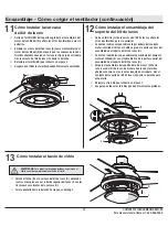
Page 29: ...es el montaje estándar del tubo bajante bola la pestaña en el aro en la parte inferior del soporte de montaje tiene que encajar en la ranura de la bola de soporte Si la pestaña no se asienta correctamente en la ranura se puede dañar el cableado Ensamblaje Cómo colgar el ventilador continuación 8 Cómo enrollar el cable sobrante Ƒ Con cuidado enrolla el exceso de cable alrededor del soporte de monta...

Page 30: ...egura que todos los tornillos queden firmemente apretados E AA F Ensamblaje Cómo colgar el ventilador continuación 9 Cómo instalar la antena WINK Ƒ Antes de instalar la antena en el techo asegúrate de que el área del techo esté limpia sin polvo ni suciedad Ƒ Retira la franja protectora de la cinta adhesiva de doble cara en la antena en forma de T y pega la antena al techo Ƒ Asegura la antena en el...

Page 31: ...ul que sobresale por debajo del conjunto motor ventilador E con el cable negro de la parte superior del ensamblado del soporte del kit de luces H Ƒ Conecta el cable blanco que sobresale por debajo del conjunto motor ventilador E con el cable blanco de la parte superior del ensamblado del soporte del kit de luces H Ƒ Empuja el ensamblaje del soporte del kit de luces H hacia la carcasa del kit de lu...

Page 32: ...me y suelta el botón para encender o apagar la luz Ƒ Si utilizas bombillas regulables y previamente configuraste el interruptor O D del control remoto en la posición D mantén presionado el botón para activar la función de regulación de intensidad 4 Comfort BreezeTM Ƒ Oprime y suelta el botón para activar la función Comfort BreezeTM esto hará que la velocidad del ventilador cambie aleatoriamente im...

Page 33: ...L ZL OH H YLHSPaHKV LS LTWHYLQHTPLU V LS LU PSHKVY LUJLUKLYm H LSVJPKHK IHQH SH S a WHYWHKLHYm LJLZ CEILING FAN Cancel Help Great now you can turn on your fan The light in your fan will blink 3 times when pairing is successful OVYH X L LS O I LZ m JVULJ HKV H W LKLZ JVU YVSHY LU PSHKVY Off 1 2 3 4 Breeze Off On FAN SPEED FAN LIGHT FANS 3 19 PM P P 53 56 Reinicia tu ventilador si el emparejamiento ...

Page 34: ...a cálido o frío dependen del tamaño de la habitación la altura del techo la cantidad de ventiladores y otros factores Ƒ Clima cálido Hacia adelante Un flujo de aire descendente surte un efecto refrescante Estotepermiteprogramarelaireacondicionadoenunaconfiguración más alta sin afectar tu comodidad Ƒ Clima frío Reversa Un flujo de aire hacia arriba mueve el aire cálido lejos del cielo raso Esto te ...

Page 35: ...pas y los tornillos de sus brazos estén bien ajustados Ƒ La mayoría de los problemas de oscilación del ventilador se deben a que las aspas no están al mismo nivel Verifica este nivel seleccionando un punto en el cielo raso sobre la punta de una de las aspas Mide desde un punto en el centro de cada aspa a un punto en el techo Rota el ventilador hasta que la siguiente aspa esté en posición para medi...

Page 36: ...la tienda llama al Servicio al Cliente de Home Depot de lunes a viernes entre 8 00 a m y 7 00 p m Hora Estándar del Este y los sábados de 9 00 a m a 6 00 p m Hora Estándar del Este 1 800 986 3460 HOMEDEPOT COM HOMEDECORATORS Conserva este manual para uso futuro ...

Reviews: