background image

12

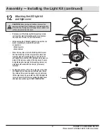
Attaching the LED light kit 
and light cover

Assembly — Installing the Light Kit (continued)

15

HOMEDEPOT.COM/HOMEDECORATORS

Please contact 1-800-986-3460 for further assistance.

CAUTION:

 Before starting installation, disconnect the 

power by turning off the circuit breaker or removing the fuse 
at the fuse box. Turning power off using the fan switch is not 
sufficient to prevent electric shock.

     Remove one of the three light kit mounting screws 

(JJ) from the light kit mounting plate (I) and loosen 
the other two screws (JJ). (Do not remove.)

     While holding the 14W LED light kit (J) under the fan 

motor assembly (F), make the 2-pin wire 
connections:

        - White to white
        - Black to black

     Place the key holes in the 14W LED light kit (J) over 

the two mounting screws (JJ) previously loosened 
from the light kit mounting plate (I). Turn the 14W 
LED light kit (J) until the 14W LED light kit (J) locks in 
place at the narrow section of the key holes. Secure 
by tightening the two light kit mounting screws (JJ) 
previously loosened and the one (JJ) previously 
removed.

     Position the notches (YY) in the outer rim of the 14W 

LED light kit (J) so they line up with the tabs (ZZ) on 
the inside of the rim on the light cover (K). Carefully 
lift the light cover (K) up inside the 14W LED light kit 
(J) and secure it to the fan by turning the light cover 
(K) clockwise until snug. DO NOT OVERTIGHTEN.

F

JJ

J

K

I

YY

ZZ

Summary of Contents for PARKRIDGE YG614-NI

Page 1: ...store call Home Decorators Collection Customer Service 8 a m 7 p m EST Monday Friday 9 a m 6 p m EST Saturday 1 800 986 3460 HOMEDEPOT COM HOMEDECORATORS Visual instruction of how to install this fan...

Page 2: ...ice Parts 16 16 17 17 18 19 Table of Contents 2 Table of Contents Safety Information Warranty Pre installation Specifications Tools Required Hardware Included Package Contents Installation Assembly Ha...

Page 3: ...ed conductors should be turned upward and pushed carefully up into the outlet box The wires should be spread apart with the grounded conductor and the equipment grounding conductor on one side of the...

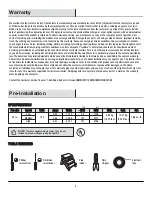
Page 4: ...ful life when protected from varying weather conditions A certain amount of wobble is normal and should not be considered a defect Servicing performed by unauthorized persons shall render the warranty...

Page 5: ...k washer preassembled Clevis pin preassembled Cotter pin preassembled Cross pin preassembled Setscrew preassembled Collar setscrew preassembled Light kit mounting plate screw preassembled Light kit mo...

Page 6: ...ing plate 14 watt LED Light kit Light cover Receiver Remote control Quantity Quantity 5 1 1 1 1 1 Part Part A B C D E F G Quantity Quantity 1 1 1 1 1 1 5 Description Description Mounting bracket preas...

Page 7: ...ways to mount the outlet box MM not included MM MM NN MM MM A Installation MOUNTING OPTIONS MOUNTING OPTIONS WARNING To reduce the risk of fire electric shock or personal injury mount the fan to an ou...

Page 8: ...od assembly D GG D FF Carefully feed the motor wires up through the downrod QQ Thread the downrod QQ into the collar Align the holes and replace the clevis pin DD and cotter pin EE Tighten the two col...

Page 9: ...to an outlet box or supporting system marked acceptable for fan support and use the mounting screws provided with the outlet box WARNING The tab in the ring must rest in the groove of the hanger ball...

Page 10: ...battery out of the reach of children Setting the Code on the Remote Remove the battery cover on the back of the remote control M by pressing firmly on the arrow and sliding the cover off Slide the cod...

Page 11: ...e white neutral wire from the ceiling to the white wire marked AC in N from the receiver L If your outlet box MM has a ground wire green or bare copper connect it to the fan ground wires otherwise con...

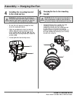
Page 12: ...on the mounting bracket A properly sits in the groove in the hanger ball downrod assembly D before attaching the canopy C to the mounting bracket A by turning the canopy C until it drops into place Sl...

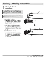
Page 13: ...rly seated on the blade arm posts SS Firmly slide the blade G away from the blade arm H until the blade G engages in the spring locking mechanism TT Make sure the spring of the spring locking mechanis...

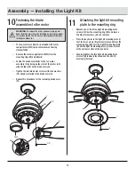
Page 14: ...VV on the blade arms H Tighten the two blade arm screws with lock washers CC already installed in the blade arms H Repeat this procedure for the remaining blade arms H 14 11 Attaching the light kit m...

Page 15: ...the fan motor assembly F make the 2 pin wire connections White to white Black to black Place the key holes in the 14W LED light kit J over the two mounting screws JJ previously loosened from the light...

Page 16: ...ease the button to turn the light on or off If you are using dimmable bulbs and you have previously set O D dip switch in your remote to the D position press and hold the button to activate the dimmer...

Page 17: ...ter when cleaning Water could damage the motor or the wood or possibly cause an electrical shock Apply oil to your fan or motor The motor has permanently lubricated sealed ball bearings Do not Do not...

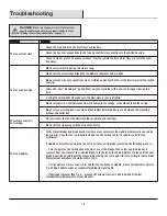
Page 18: ...t rubber isolator pads are used between the mounting bracket and outlet box The fan will not start The fan sounds noisy WARNING Make sure the power is off at the electrical panel box before you attemp...

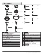
Page 19: ...ption Description Plastic wire nut Canopy mounting screw with lock washer preassembled Blade arm screw with lock washer preassembled Clevis pin preassembled Cotter pin preassembled Cross pin preassemb...

Page 20: ...arts Before returning to the store call Home Decorators Collection Customer Service 8 a m 7 p m EST Monday Friday 9 a m 6 p m EST Saturday 1 800 986 3460 HOMEDEPOT COM HOMEDECORATORS Retain this manua...

Reviews: