27
1/2 HP Chain Drive Garage Door Opener
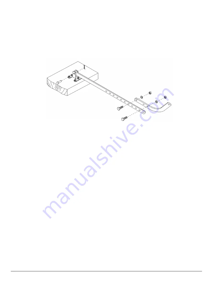
4. Attach the straight bracket to the curved bracket with the longest possible length, so there is a 3-hole
overlap as shown below. Secure the two sections together with two bolts (M6-45), two spring washers and
two nuts (M8).
5. Fasten the end of the straight arm section to the door bracket using the clevis pin (
∅
8-35) and split pin as
shown.
Note: Before connecting the door arm to the trolley, you must adj ust the up and dow n travel limits first.
One full turn on the travel adj ustment screw s equals approximately 2” of trav el adj ustment. For further
trav el limit adj ustment description, refer to “Testing & Adj usting the Door Range of Motion” ahead.
Adjusting the UP Travel Limit: (see next page for drawing)
1. Turn the UP travel adjustment screw counterclockwise 5 complete turns (increasing the UP travel limit)
2. Press the door control push button on the Premium Control Console so the trolley will travel to the fully
open position.
3. Manually raise the door to the open position so the door is parallel with the garage floor. If the door has a
downward slope when opened, you have opened the door too far. The end of the curved arm section
should be close to the trolley door arm connector hole.
4. If the arm does not extend far enough to attach to the trolley, adjust the travel limit further.
Adjusting the DOWN Travel Limit: (see next page for drawing)
1. Turn the DOWN travel adjustment screw clockwise 5 complete turns (decreasing the DOWN travel limit)
2. Press the door control push button so the trolley will travel the fully closed position.
3. Manually close the door all the way. The end of the curved arm section should be next to the trolley door
arm connector hole.
4. If the arm does not extend far enough to attach to the trolley, adjust the travel limit further.


