background image

WARNING: SHUT POWER OFF AT FUSE OR CIRCUIT BREAKER

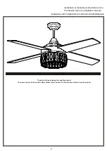
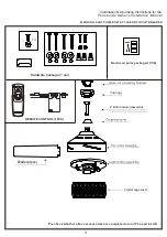
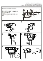
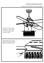
Installation & Operating Instructions for the 

Parrotuncle Owner's Installation ,Manual

8

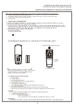
Remote  controller

GENERAL  INFORMATION

This remote controller is designed to separately control your ceiling fan speed and light ON/OFF.

There are four buttons (HI, MED, LOW, OFF) to control the speed of the fan and off.

The light button will control the light on and off.

The red indicator on the transmitter will light when one of the nine buttons is pressed.

INSTRUCTION OF INSTALLATION AND OPERATION

2.INSTALLING RECEIVER IN CEILING FAN

 A. Safety precautions:

WARNING: HIGH VOLTAGE!  Disconnect power by

removing fuse or switching off circuit breaker.

Do not use with solid state fans.

Electrical wire must meet all local and national

electrical code requirements.

Supply for fan must be 220/240 volt, 50Hz. Maximum

       fan motor amps: 1.0, Maximum light watts: 180

       incandescent or ballast.

      Otherwise power can cause serious injury or death.

B. Installing receiver in fan:

a. emove power from the circuit.

b. emove ceiling fan canopy from the mounting

bracket.

c. isconnect existing wiring between ceiling fan and

Supply in electrical junction box.

d. ake connections as follows, using the wire nuts

supplied:

For Mounting Controller,  Model  RE-026

CONNECT     TO

Green fan wire ....Bare supply wire

Brown receiver wire(AC IN L) ....Brown  supply wire

Blue receiver wire(AC IN N) ....Blue supply wire

Blue receiver wire(TO MOTOR N) ....Blue fan wire

Brown receiver wire(TO MOTOR L) ....Brown fan wire

Black/Orange receiver wire(FOR LIGHT) ....Black/Orange light wire

CAUTION: Ceiling Angle Shall Not Exceed 30 Degrees,

FIG1

ACN

ACL

ANT

COM

FAN

LIGHT

INPUT

OUTPUT

RECEIVER

Use wire connecting nuts supplied  with the fan

(FIG.3)

FROM POWER SOURCE 

AC 220~240 VOLT 50Hz 

.

Use wire connecting nuts 

supplied with the remote 

controller.

WIRE NUT

RECEIVER

CANOPY

(FIG.4)

ANTENNA PUT AT OUTSIDE 

OF CANOPY BOX CAN GET 

MORE OPERATION 

DISTANCE

BLUE

INPUT

OUTPUT

 BROWN

ANT

CANOPY

RECEIVER

BLUE

 BROWN

BLACK OR ORANGE

1.SETTING THE CODES

To set the codes, perform the following steps:

 A. Setting the codes on the transmitter:

a. emove battery cover. Press firmly on the arrow and slide battery cover off.

b. lide code switches to your choice of up or down position. (Factory setting is all up. Do not use this position. Use a

Small screwdriver or ball point pen to slide firmly up or down (Figure 1)).

B. Setting the codes on the receiver:

The Learn Key must be pressed with in 30 seconds, after pressing the Power button.

If not, please press the Power button to restart.

Keep pressing the button learn key  in excess of 3 second it becomes a LEARN status.

The receiver can remember the last codes  status .The light flash two times.

TRANSMITTER

LEARN

CODE

COM

CODE

Summary of Contents for F6277110V

Page 1: ...CEILING FAN ...

Page 2: ... competent person 11 This appliance can be used by children aged from 8 years and above and persons with reduced physical sensory or mental capabilities or lack of experience and knowledge if they have been given supervision or instruction concerning use of the appliance in a safe way and understand the hazards involved Children shall not play with the appliance Cleaning and user maintenance shall...

Page 3: ...T BREAKER 2 Installation Operating Instructions for the Parrotuncle Owner s Installation Manual Thank you for purchasing this quality product To ensure correct function and safety please read and save all instructions before using the product ...

Page 4: ...eted or not Yes and install REMOTE CONTROL 1PCS Installation Operating Instructions for the Parrotuncle Owner s Installation Manual WARNING SHUT POWER OFF AT FUSE OR CIRCUIT BREAKER 4 Ball downrod assembly Blades 4pcs Crystal cage cover 3g 3g 3g Hardware package 1 set 3 X13 ...

Page 5: ...ting holes in the ceiling joist and securely screw the mounting bracket to the ceiling using the washers and wood screws provided The mounting plate should be able to hold a weight of at least 15 9kgs 35 lbs NOTE Proper care must be taken when mounting to concrete ceilings For safe mounting these ceilings may require stronger screws and plastic plugs or anchors than supplied with the product 2 ...

Page 6: ... CIRCUIT BREAKER Installation Operating Instructions for the Parrotuncle Owner s Installation Manual 8 9 7 B A 5 1 2 3 AC POWER IN PUT TO FAN WIRES L N 10 Remove the 3 screws shown as above figure before taking down the top housing 11 ...

Page 7: ...les Insert 3pcs blade screws and washers with fingers Tighten securely with a phillips screwdriver Repeat for the remaining blades 6 WINTER TIME SUMMER TIME d A warm weather Forward A Downward airflow creates a cooling effect This allows you to set your air conditioner on a higher setting without affecting your comfort B Cool weather Reverse An upward airflow moves warm air off the ceiling This allows ...

Page 8: ...ng Instructions for the Parrotuncle Owner s Installation Manual 7 Rotate 3 E12 bulbs into the lamp holders Attach the light kit cage to the light kit plate using the 4 screws Align the tooth hole on the light plate with the hole on the crystal cage cover and tighten screw ...

Page 9: ... RE 026 CONNECT TO Green fan wire Bare supply wire Brown receiver wire AC IN L Brown supply wire Blue receiver wire AC IN N Blue supply wire Blue receiver wire TO MOTOR N Blue fan wire Brown receiver wire TO MOTOR L Brown fan wire Black Orange receiver wire FOR LIGHT Black Orange light wire CAUTION Ceiling Angle Shall Not Exceed 30 Degrees FIG1 ACN ACL ANT COM FAN LIGHT INPUT OUTPUT RECEIVER Use w...

Page 10: ...ver D Operating the buttons on the panel of the transmitter 3 key for fan high speed 2 key for fan medium speed YOUR REMOTE NOW HAS FULL CONTROL OF THE FAN AND LIGHT OPERATION DISTANCE 20 FEET TRANSMITTER MODEL RE 011 Optional Wall Mounting for Transmitter Holder Place in accessible area of your home and screw the transmitter holder into wall using the two screws provided slide hand unit into hold...

Page 11: ...WARNING SHUT POWER OFF AT FUSE OR CIRCUIT BREAKER size of product Installation Operating Instructions for the Parrotuncle Owner s Installation Manual 10 5 2 i n ...

Page 12: ...sing a Variable Speed Wall Switch ensure it is specifically designed for use with a ceiling fan Check the line wire connec ons to the fan and the switch wire connec ons in the switch housing per the instruc ons 2 THE FAN IS NOISY Make sure all motor housing screws are ghtened Make sure the screws that a ach fan blade to motor are ght Make sure the wire nut connectors are not ra ling against each ot...

Page 13: ...measure from the center of the selected blade to point on the ceiling Rotate the fan un l the next blade is posi oned and repeat the measurement using the same point from the ceiling for every blade Measurements should be within 1 8 inch 4 LIGHT IS NOT WORKING Check Bulb to make sure it is installed correctly Remove non working bulb and replace with a bulb that is known to be a good working bulb T...

Page 14: ...ble is still noticeable 4 If the blade wobble is still noticeable interchanging two adjacent side by side blades can redistribute the weight and possibly result in smoother operation WARNING TO REDUCE THE RISK OF PERSONAL INJURY DO NOT BEND THE BLADE ARM WHILE INSTALLING BALANCING THE BLADES OR CLEANING THE FAN DO NOT INSERT FOREIGN OBJECTS BETWEEN ROTATING FAN BLADES NOISE When it is quiet especi...

Reviews: