background image

Top Plate

W5-C

W3

W5-C

W5

W5

W5

W3

W5-C

W5-C

W3

W5

W3

W5-X

W3-HX

K35-8R

K35-8M

K35-8M

K35-8L

10

Summary of Contents for G37007

Page 1: ......

Page 2: ...We offer a diverse range of products to meet the needs of customers We continue to supply high quality and reliable products while maintaining a balance of price and product and strive to provide consumers with quality at a good price ...

Page 3: ...ls in the order specified in the instructions All lines and holes must be accurately matched to make the storage shed more stable Please ensure that all screws are tightened to prevent the product from falling apart There is a protective film on the surface to protect the product please tear it off after installation to get the final presentation lf you do not damage the film during installation it can...

Page 4: ...crews buckles and straps every 90 days Please keep all screws loose during the assembly process and tighten them after completing the installation Do not use or store objects in the Metal Shed with open flames or flammable chemicals Please note that some parts have sharp edges and should be handled with gloves If any parts are missing broken damaged or worn discontinue use of the product until repai...

Page 5: ...K35 1 K35 2 K35 3 K35 4 K35 5 ULA URA K35 6L K35 6R K35 7 K35 9 K35 10L K35 10R K35 11L K35 11R DD DLA1 DRA1 5 ...

Page 6: ...DX1 W5 X W3 HX W5 C W5 W3 K35 8L K35 8M K35 8R GC T F DCS C2 DH 6 GF ...

Page 7: ...HARDWARE F1 198PCS F2 39PCS F3 16PCS V2 189PCS 42PCS 1PC SL M4 ST 2PCS 7 ...

Page 8: ...Part List K35 9 GC GC K35 8L K35 8M K35 8M K35 8R K35 9 GC GC K35 10L K35 10R K35 11R K35 11L 8 GF GF K35 6L C2 C2 K35 3 K35 7 K35 5 K35 4 C2 K35 3 C2 K35 6R GF ...

Page 9: ...W5 C W5 C W3 W3 W5 W5 W5 W5 C W5 C W3 URA W3 HX DCS DX1 DX1 DD DD W5 X W3 W5 ULA DLA1 T F T F T F T F K35 2 K35 2 K35 1 K35 1 Part List 9 DRA1 ...

Page 10: ...Top Plate W5 C W3 W5 C W5 W5 W5 W3 W5 C W5 C W3 W5 W3 W5 X W3 HX K35 8R K35 8M K35 8M K35 8L 10 ...

Page 11: ...F1 V2 Shed Base Frame Assemble Link the two K35 1 and K35 2 to each other and reinforce the four corners with T F T F T F T F T F K35 2 K35 2 K35 1 K35 1 V2 F1 V2 V2 F1 V2 F1 11 ...

Page 12: ...Shed Side Panels Assemble Mount the 4 W5 C on the Shed Base Frame Assemble as shown 2 W5 C W5 C W5 C W5 C W5 C W5 C W5 C W5 C W5 C W5 C W5 C F1 V2 12 ...

Page 13: ...on W5 C as shown 3 Link K35 4 and K35 5 with K35 3 using 4 C2 4 W5 C W5 C W5 C W5 C K35 3 K35 4 W5 C W5 C W5 C W5 C K35 4 K35 3 K35 3 K35 4 K35 3 K35 5 K35 4 K35 3 K35 3 K35 5 K35 5 K35 3 C2 F1 V2 F1 V2 C2 F1 V2 16 16 13 ...

Page 14: ...Install three W5 on K35 4 5 Install the remaining W3 W5 according to the diagram F1 V2 W5 C W5 C W5 C W5 C W5 W5 W5 F2 F2 F1 V2 F1 V2 F2 W5 W5 W5 W3 W5 W3 W3 W5 C W5 C W5 C W5 C W3 14 ...

Page 15: ...Install ULA on the left side of the door frame and URA on the right side of the door frame 7 F2 F1 V2 F1 V2 ULA ULA ULA URA URA V2 F1 F1 V2 W5 W5 W5 W5 W3 W3 W3 W3 W5 C W5 C W5 C W5 C URA ULA 15 ...

Page 16: ...ssemble Install GF on two K35 6 K35 6L is mounted on the top left K35 6R is mounted on the top right 8 Install the K35 7 on top of the front 9 F1 V2 K35 6L K35 6R F2 K35 7 F1 V2 K35 7 K35 6L K35 6R K35 7 16 F2 F2 GF GF ...

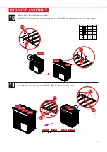
Page 17: ... mounted on the top left K35 8R is mounted on the top right 10 Install the remaining two K35 8M in the ceiling void 11 F1 V2 K35 8L K35 8L K35 8R F1 V2 K35 8L K35 8M K35 8M K35 8R F1 V2 K35 8M K35 8M F1 V2 K35 8M K35 8M K35 8L K35 8R 17 ...

Page 18: ...0R and K35 10L on the rear side of the roof 3 Connect and install K35 11R and K35 11L on the front side of the roof 4 Install the corner GC on the four corners of the roof 12 F1 V2 K35 9 K35 9 K35 9 K 3 5 9 K35 10R GC V2 F1 V2 F1 F2 K35 10R K35 10L K35 11R K35 11L GC GC GC GC 18 ...

Page 19: ...13 19 1 Combine W5 X and W3 HX into a door 2 Install DD DLA1 and DRA1 around F2 W5 X W3 HX DLA1 DD DRA1 DD F1 ...

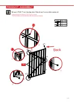
Page 20: ...13 Mount DX1 on the back of the door for reinforcement 20 F2 F1 DX1 ...

Page 21: ...1 Install the two DH hinges on one side of the door using 8 F3 screws 2 Use 6 F2 screws to fasten the DCS part to the door as shown 14 DH F3 F2 DCS 21 ...

Page 22: ...1 Use 8 F3 screws to mount the door in the position shown 2 Use 2 F2 screws to mount the DCS part in the position shown 15 F2 DCS F3 22 ...

Page 23: ...The exposed parts of the screws need to be covered with plastic protective caps Screw positions Exposed parts of ceiling and k35 7 assembly screws 16 SL 23 ...

Page 24: ...24 ...

Reviews: