background image

1

7

A

B

1

2

3

A1

4

A2

1

2

3

B1

1

2

B2

B5

1

3

3

2

2

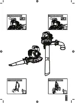
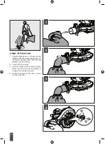
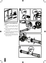
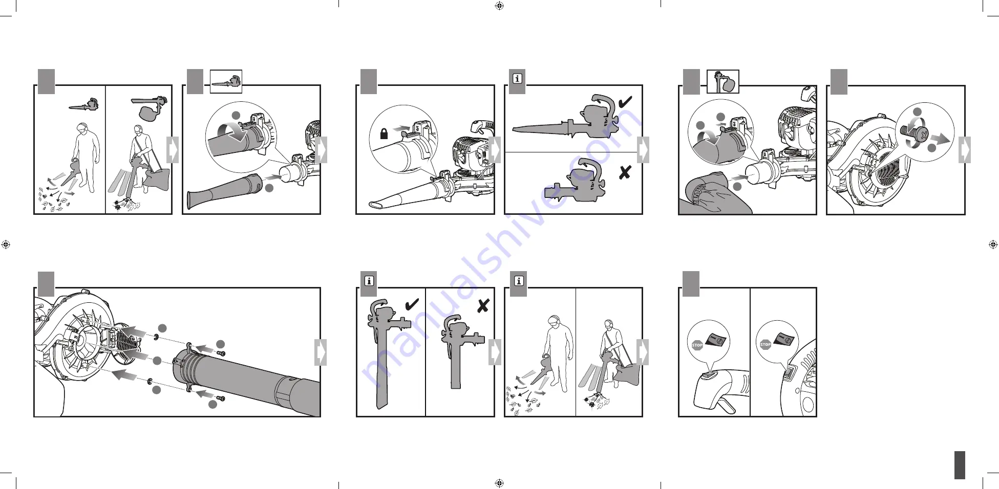
1. 

Align raised tabs on upper blower tube with the slots on

blower housing outlet. 

2.

 Attach and tighten securely by

turning clockwise until it clicks into place. 

A. 

Attach the blower tube. 

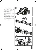
B.

 Attach the vacuum tubes.

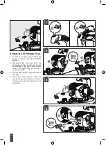
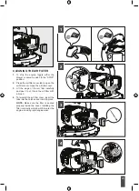
Press slider plate into positive switch’s slot.

1. 

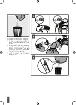
Align the raised slots on the vacuum bag adaptor with

the raised locking tabs on the blower housing outlet; push

the bag adaptor onto the housing. 

2. 

Twist to lock into

place.  

3. 

 Press the slider plate into the positive switch slot 

to make sure the switch is engaged and ready to operate.

1. 

Depress door tab using a flat head screwdriver.

2. 

Loosen the screw on the door to open vacuum inlet door.

1. 

Align tabs on housing with the vacuum tube assembly. 

2. 

 Tighten screws on upper vacuum tube to secure to blower

housing.

A.

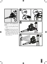
 Hold the blower with the upper handle in your right hand. 

Place the vacuum bag strap over your right shoulder. Hold

the upper handle in your left hand and the vacuum handle

in your right hand.

To stop the engine, toggle either the blower or vacuum 

switch to the “STOP” position.

NOTE:

 Ensure to attach the blower tube securely to the 

blower/vacuum housing.

NOTE:

 Ensure to attach the vacuum tubes securely to the 

blower/vacuum housing.

Summary of Contents for HBL26BVB

Page 1: ...HBL26BVB ...

Page 2: ...Important It is essential that you read the instructions in this manual before assembling operating and maintaining the product Subject to technical modifications ...

Page 3: ...a closed or poorly ventilated area breathing exhaust fumes can kill Clear the work area before each use Remove all objects such as rocks broken glass nails wire or string that can be blown a considerable distance by high velocity air Wear hearing protection at all times while operating the product The product is noisy and permanent hearing injury may result if precautions to limit your exposure re...

Page 4: ...r unstable support Stable footing on a solid surface enables better control of the blower in unexpected situations Never use the product with defective guards or shields or without safety devices in place Do not modify the product in any way or use parts and accessories that are not recommended by the manufacturer WARNING Before using the product in vacuum mode you must assemble the upper and lowe...

Page 5: ...stream can work close to the ground and perform effectively Do not point the blower nozzle in the direction of people or pets Never place objects inside the blower tubes Do not place the product on top of or near loose debris Debris can be sucked into the intake vent resulting in possible damage to the product VACUUM SAFETY WARNINGS WARNING Never operate the vacuum with only the upper vacuum tube ...

Page 6: ...t against movement or falling to prevent injury to persons or damage to the product Abide by all government and local regulations for the safe storage and handling of petrol Short term less than 1 month Stop the engine and allow the product to cool down before storing or transporting Clean all foreign material from the product Store the product in a cool dry and well ventilated place that is inacc...

Page 7: ...ury from flying objects from the blow tube airflow Wear eye protection at all times RISK REDUCTION It has been reported that vibrations from handheld tools may contribute to a condition called Raynaud s Syndrome in certain individuals Symptoms may include tingling numbness and blanching of the fingers usually apparent upon exposure to cold Hereditary factors exposure to cold and dampness diet smok...

Page 8: ...ny speed between idle and full throttle VACUUM Converting the blower to a vacuum is simple and can be done using a cross head screwdriver VACUUM BAG The vacuum bag attaches to the blower easily by using the vacuum bag adaptor VACUUM HANDLE This feature allows the user to perform vacuuming duties comfortably VACUUM TUBES The vacuum tubes can be installed on the blower using a cross head screw drive...

Page 9: ...y WARNING Always wear eye protection with side shields marked to comply with standards along with hearing protection Failure to do so could result in serious injuries such as objects being thrown into your eyes MIXING THE FUEL The product is powered by a 2 stroke engine and requires premixing petrol and 2 stroke oil The mixture should be at a 50 1 ratio NOTE We recommend you use RYOBI synthetic 2 ...

Page 10: ...ng fuel cap is a fire hazard and must be replaced immediately If you find any leaks correct the problem before using the product Failure to do so could result in a fire that could cause serious personal injury OXYGENATED FUELS Do not use E85 fuel It will void your warranty NOTE Fuel system damage or performance problems resulting from the use of an oxygenated fuel containing more than the percenta...

Page 11: ...d cars and blow debris safely away USING THE VACUUM See page 26 WARNING Keep the silencer and all hot surfaces of the blower vacuum away from your body Failure to do so could result in possible serious personal injury Place the vacuum bag strap over your right shoulder Hold the upper handle in your left hand and the vacuum handle in your right hand Move the blower vacuum from side to side along ou...

Page 12: ...sure proper performance of your product FUEL CAP WARNING A leaking fuel cap is a fire hazard and must be replaced immediately The fuel cap contains a non serviceable filter and a check valve A clogged fuel filter will cause poor engine performance If performance improves when the fuel cap is loosened check valve may be faulty or filter clogged Replace fuel cap if required CLEANING THE VACUUM BAG S...

Page 13: ... The product meets applicable regulatory requirements Waste electrical products should not be disposed of with household waste Please recycle where facilities exist Check with your local authority or retailer for recycling advice The following signal words and meanings are intended to explain the levels of risk associated with this product DANGER Indicates an imminently hazardous situation which i...

Page 14: ...ged ready to work and the on off switches are in the run I position Contact authorised service centre Engine hard to start Water in petrol or stale fuel mixture Drain entire system and refill with fresh fuel Water in petrol or stale fuel mixture Drain and refill with correct mixture Engine is under or over choked Adjust choke as necessary Weak spark at spark plug Contact authorised service centre ...

Page 15: ...Original instructions English 13 ...

Page 16: ...14 x 1 x 1 x 1 x 1 x 1 x 1 x 1 ...

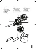
Page 17: ... for vacuum mode 4 Starter grip 5 Fuel cap 6 Vacuum grip handle 7 Choke lever 8 Primer bulb 9 Positive switch at vacuuming side 10 Vacuum inlet door 11 Vacuum bag adaptor 12 Vacuum bag 13 Lower vacuum tube 14 Upper vacuum tube 15 Blower tube 16 Positive switch at blowing side 17 Spark plug 18 Throttle trigger ...

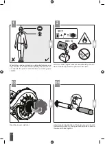
Page 18: ...l eye and ear protection substantial footwear and long trousers at all times while operating the product Do not operate the product when barefoot or wearing open sandals Open the vacuum inlet door Align the raised locking tabs of the lower vacuum tube with the matching orifice on the upper vacuum tube to secure the vacuum tubes together ...

Page 19: ...ve switch slot to make sure the switch is engaged and ready to operate 1 Depress door tab using a flat head screwdriver 2 Loosen the screw on the door to open vacuum inlet door 1 Align tabs on housing with the vacuum tube assembly 2 Tighten screws on upper vacuum tube to secure to blower housing A Hold the blower with the upper handle in your right hand Place the vacuum bag strap over your right s...

Page 20: ...18 ...

Page 21: ...19 Cold start engine Warm start engine Using the blower Using the vacuum p 21 p 25 p 23 p 26 ...

Page 22: ...20 Replacing the spark plug Cleaning the air filter Cleaning the vacuum bag Cleaning the blower vacuum Storing the blower vacuum p 28 p 29 p 31 p 30 p 32 ...

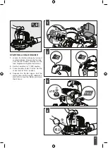
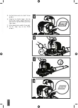
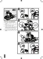
Page 23: ...uel cap Pour the fuel mixture carefully into the tank Replace and tighten the fuel cap 2 Set the 2 switches to I ON position 3 Press the primer bulb 10 times Set the choke lever to FULL position 4 Squeeze the throttle trigger Pull the starter grip until the engine attempts to start Do not pull the starter grip more than 8 times ...

Page 24: ... the HALF choke position 6 Squeeze the throttle trigger Pull the starter grip until the engine attempts to start Do not pull the starter grip more than 6 times 7 When engine starts wait for 10 seconds 8 Set the choke lever to the RUN position ...

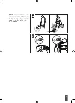
Page 25: ...23 9 NOTE Hold blower as shown so the air stream can work close to the ground 9 To stop the engine toggle either the blower or vacuum switch to the STOP position ...

Page 26: ... position 2 Press the primer bulb 10 times Set the choke lever to RUN position 3 Squeeze the throttle trigger Pull the starter grip until the engine starts Do not pull the starter grip more than 6 times 4 To stop the engine toggle either the blower or vacuum switch to the STOP position ...

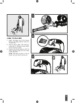
Page 27: ...ion for the procedure 2 Start the blower Refer to the Starting a cold engine or Starting a warm engine section for the procedure 3 Squeeze the throttle trigger to start the blower Hold the blower with the handle in your right hand NOTE Hold blower as shown so the air stream can work close to the ground ...

Page 28: ...h the raised locking tabs on the blower housing outlet push the bag adaptor onto the housing 2 Twist to lock into place 3 Press the metal contact into the positive switch slot to make sure the switch is engaged and ready to operate 4 Loosen the screw on the door to open vacuum inlet door ...

Page 29: ... the blower tubes are secured 7 Align tabs on housing with vacuum tube assembly Tighten screws on upper vacuum tube to secure to blower housing 8 Start the blower Refer to the Starting a cold engine or Starting a warm engine section for the procedure Squeeze the throttle trigger to start the vacuum NOTE Place the vacuum bag strap over your right shoulder Hold the upper handle in your left hand and...

Page 30: ...isconnect the lead wire from the spark plug Using a socket wrench with an extension and spark plug socket loosen the spark plug by turning it counterclockwise 3 Remove the old spark plug and dispose properly 4 Using the socket wrench install the new spark plug and tighten by turning it clockwise Connect the lead wire to the spark plug ...

Page 31: ...ilter cover Open the air filter cover 3 Lift the edge of the air filter carefully and peel it out Clean the air filter with a brush 4 To reinstall the air filter cover insert the tabs into the notches and lock into place NOTE Make sure the filter is seated properly inside the cover Installing the filter incorrectly will allow dirt to enter the engine causing rapid engine wear ...

Page 32: ... the blower or vacuum switch to the STOP position 2 To remove the vacuum bag and adaptor pull off the metal contact twist the adaptor counterclockwise and then remove the vacuum bag and adaptor from the blower housing outlet 3 Unzip the vacuum bag and dispose debris properly ...

Page 33: ...h to the STOP position 2 Clean the blower vacuum using a brush WARNING Avoid using solvents when cleaning plastic parts Most plastics are susceptible to damage from various types of commercial solvents and may be damaged by their use Use clean cloths or brush to remove dirt dust lubricant grease etc ...

Page 34: ...switch to the STOP position A1 To remove the blower tube twist and remove the tube from the blower housing outlet B1 To remove the vacuum tube assembly loosen the screws that secure the tube assembly to the inlet cover B2 Press on the raised locking tab and then detach the upper vacuum tube from the lower vacuum tube ...

Page 35: ...lockwise and then remove the vacuum bag and adaptor from the blower housing outlet 2 Loosen the fuel cap slowly by turning counterclockwise and then drain all fuel from the tank into a container approved for fuel After draining all the fuel replace the fuel cap and tighten by turning it clockwise 3 Store blower vacuum and its parts in a cool dry and well ventilated place that is inaccessible to ch...

Page 36: ...eclared vibration value has been measured with a standard test method and may be used to compare one tool with another The declared vibration value may be used in a preliminary assessment of exposure The vibration emission during actual use of power tool can differ from the declared total value depending on the ways in which the tool is used Identify safety measures to protect yourself based on an...

Page 37: ......

Page 38: ......

Page 39: ......

Page 40: ...60704016 01 Techtronic Industries Australia Pty Ltd 31 Gilby Road Mount Waverly VIC 3149 Melbourne Australia Techtronic Industries NZ Limited 2 Landing Drive Mangere Auckland 2022 New Zealand Imported by ...

Reviews: