background image

Page  

FEATURES

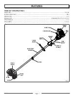
KNOW yOUR EDGER

See Figure 1.

The safe use of this product requires an understanding of 
the information on the tool and in this operator’s manual as 
well as a knowledge of the project you are attempting. Before 
use  of  this  product,  familiarize  yourself  with  all  operating 
features and safety rules.

TOP-MOUNTED MOTOR

The top-mounted motor improves balance and is located 
away from the dust and debris of the cutting area.

ASSEMBLy

UNPACKING

This product requires assembly.

  Carefully remove the product and any accessories from 

the box. Make sure that all items listed in the packing list 
are included.

  Inspect the product carefully to make sure no breakage 

or damage occurred during shipping.

  Do not discard the packing material until you have care-

fully inspected and satisfactorily operated the product.

  If  any  parts  are  damaged  or  missing,  please  call 

1-800-242-4672 for assistance.

PACKING LIST

Edger Assembly
Handle Assembly
Holding Pin
Hanger Cap
Bottle of 2-Cycle Lubricant
Operator’s Manual

WARNING:

If any parts are damaged or missing, do not operate this 
product until the parts are replaced. Failure to heed this 
warning could result in serious personal injury.

WARNING: 

Do not attempt to modify this product or create acces-
sories not recommended for use with this product. Any 
such alteration or modification is misuse and could result 
in  a  hazardous  condition  leading  to  possible  serious 
personal injury.

WARNING:

To prevent accidental starting that could cause serious 
personal injury, always disconnect the engine spark plug 
wire from the spark plug when assembling parts.

INSTALLING THE POWER HEAD TO THE 

 ATTACHMENT

See Figure .

WARNING:

Never  install,  remove,  or  adjust  any  attachment  while 
power head is running. Failure to stop the engine can 
cause serious personal injury.

The attachment connects to the power head by means of 
a coupler device.

  Loosen the knob on the coupler of the power head shaft 

and remove the end cap from the attachment.

  Push in the button located on the attachment shaft. Align 

the button with the guide recess on the power head coupler 
and slide the two shafts together. Rotate the attachment 
shaft until the button locks into the positioning hole.

Fig. 2

cOUPLER

kNOB

ATTAcHMENT SHAFT

POSITIONING 

HOLE

GUIDE 

REcESS

BUTTON

POwER HEAD

SHAFT

Summary of Contents for MIGHTYLITE UT50500

Page 1: ...engineered and manufactured to our high standard for dependability ease of operation and operator safety Properly cared for it will give you years of rugged trouble free performance Thank you for your purchase WARNING To reduce the risk of injury the user must read and understand the operator s manual before using this product ...

Page 2: ...ntenance 13 15 Troubleshooting 16 17 Warranty 18 20 Parts Ordering Service Back Page INTRODUCTION TABLE OF CONTENTS This product has many features for making its use more pleasant and enjoyable Safety performance and dependability have been given top priority in the design of this product making it easy to maintain and operate ...

Page 3: ...om any moving part DANGER Rotating Cutting MEMBER Keep both hands on handles when blade is rotating Keep feet away from cutting area Do not attempt to remove cut material nor hold material to be cut when engine is running or when cutting member is moving Make sure spark plug is disconnected when clearing jammed material from cutting member CAUTION Cutting member coasts after turn off Do not touch ...

Page 4: ... disconnect from power supply before attempting to remove any obstruction caught or jammed in the blade installing attachment or making any adjustments To reduce the risk of fire do not allow excessive grass leaves or grease to accumulate on the product Do not attempt to remove cut material nor hold material to be cut when the engine is running or when the cutting blade is moving Always keep your ...

Page 5: ...stand operator s manual before using this product Wear Eye and Hearing Protection Wear eye protection which is marked to comply with ANSI Z87 1 as well as hearing protection when operating this equipment Keep Bystanders Away Keep all bystanders at least 50 ft away Ricochet Thrown objects can ricochet and result in personal injury or property damage Gasoline and Lubricant Use unleaded gasoline inte...

Page 6: ...ich can result in severe eye damage Before beginning power tool operation always wear safety goggles or safety glasses with side shields and when needed a full face shield We recommend Wide Vision Safety Mask for use over eyeglasses or standard safety glasses with side shields Always use eye protection which is marked to comply with ANSI Z87 1 The following signal words and meanings are intended t...

Page 7: ...cc Blade Length 9 in Edging Depth Adjustable from 2 in to 3 1 2 in Wheel Diameter 4 in Wheel Width 1 1 4 in Fig 1 THROTTLE TRIGGER STARTER GRIP FRONT HANDLE DRIVE SHAFT HOUSING BLADE edger guard choke DIAL PRIMER BULB REAR HANDLE knob on off switch trigger lock fuel tank debris flap wheel ...

Page 8: ...re damaged or missing do not operate this product until the parts are replaced Failure to heed this warning could result in serious personal injury WARNING Do not attempt to modify this product or create acces sories not recommended for use with this product Any such alteration or modification is misuse and could result in a hazardous condition leading to possible serious personal injury WARNING T...

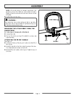
Page 9: ... check it periodically for tightness during use to avoid serious personal injury removing the attachment from the power head For removing or changing the attachment Loosen the knob Push in the button and twist the shafts to remove and separate ends ATTACHING THE FRONT handle See Figure 3 Loosen and remove the wing nut washer and bolt from the handle Install the handle on the drive shaft housing at...

Page 10: ...n US Do not use automotive lubricant or 2 cycle outboard lubri cant NOTE Premium Exact Mix fuel mix will stay fresh up to 30 days DO NOT mix quantities larger than usable in a 30 day period PREMIUM EXACT MIX 50 1 Gasoline Lubricant 1 gallon US 2 6 oz 1 liter 20 cc 20 ml FILLING TANK Clean surface around fuel cap to prevent contamination Set product on its side so that the spout points up Loosen fu...

Page 11: ...ht NOTE Always operate at full throttle Prolonged cutting at partial throttle will result in lubricant dripping from the muffler OPERATING TIPS The edger will edge along sidewalks driveways flower beds curbs and similar areas Use the arrow guide on the blade guard to align the blade with the edging surface Cut at a steady pace If the blade begins to bog down you are edging too fast slow your pace ...

Page 12: ...e wheel arm up to increase the depth or down to decrease the depth After adjustment is complete tighten the adjusting knob securely Reconnect the spark plug wire and start the unit NOTE Adjust the blade depth from 1 2 in to 1 in deep initially Make a shallow cut to test the cutting depth If the cutting depth needs adjusting this should be done progres sively until the desired depth is reached Fig ...

Page 13: ...s personal injury Stop the engine whenever you leave the operating position Disconnect the spark plug lead before unclogging the cut ting member guard or when making a repair adjustment inspection or the like Keep all nuts bolts and screws tight You can often make adjustments and repairs described here For other repairs have the product serviced by an authorized service dealer replacing the blade ...

Page 14: ...ver end of the lower end attachment shaft Slightly rotate the cap from side to side until the button locks into place The secondary hole in the attachment shaft can be used for hanging purposes as well CLEANING THE EXHAUST PORT Depending on the type of fuel used the type and amount of lubricant used and or your operating conditions the exhaust port may become blocked with carbon deposits If you no...

Page 15: ...he fuel cap is loos ened check valve may be faulty or filter clogged Replace fuel cap if required SPARK PLUG This engine uses a Champion RCJ6Y or equivalent spark plug with 025 in electrode gap Use an exact replacement and replace annually or more frequently if necessary STORing the product Clean all foreign material from the product Store it in a well ventilatedplacethatisinaccessibletochildren K...

Page 16: ...with choke dial at RUN If engine does not start rotate choke dial to FULL CHOKE position and repeat normal starting procedure If engine still fails to start repeat procedure with a new spark plug Contact a servicing dealer Engine starts but will not accelerate Engine requires approximately three minutes to warm up Allow engine to completely warm up If engine does not accelerate after three minutes...

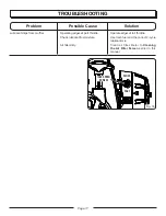
Page 17: ...fler Operating edger at part throttle Check lubricant fuel mixture Air filter dirty Operate edger at full throttle Use fresh fuel and the correct 2 cycle lubricant mix Clean air filter Refer to Cleaning the Air Filter Screen earlier in this manual Fig 16 SLOW FAST idle speed screw ...

Page 18: ...ranty does not extend to repairs made necessary by normal wear or by the use of parts or accessories which are either incompatible with the homelite brand product or adversely affect its operation performance or durability In addition this warranty does not cover A Tune ups Spark Plugs Carburetor Carburetor Adjustments Ignition Filters B Wear items Bump Knobs Outer Spools Cutting Lines InnerReels ...

Page 19: ... warranted part that is not scheduled for replacement as required in the Emissions Maintenance Schedule and Warranty Parts List set forth below is warranted for two years If any such part including any part that is scheduled only for regular inspec tion fails during the period of warranty coverage it will be repaired or replaced at any HOMELITE Authorized Service Center at no charge Any such part ...

Page 20: ...elow MAKE THE MOST OF YOUR PURCHASE Go to www homelite com and register your new tool on line Your product has been fully tested prior to shipment to ensure your complete satisfaction For any questions about operating or maintaining your product call the Homelite Help Line CALL 1 800 242 4672 www homelite com To register your Homelite product or set up your eBox account by regular mail please prin...

Page 21: ...NOTES ...
Page 22: ...ing service or purchasing replacement parts please obtain your model and serial number from the product data plate MODEL NUMBER SERIAL NUMBER How to obtain Replacement Parts Replacement parts can be purchased online at www homelite com or by calling 1 800 242 4672 Replacement parts can also be obtained at one of our Authorized Service Centers How to locate an Authorized Service Center Authorized S...

Reviews: