background image

Page 18

Note:

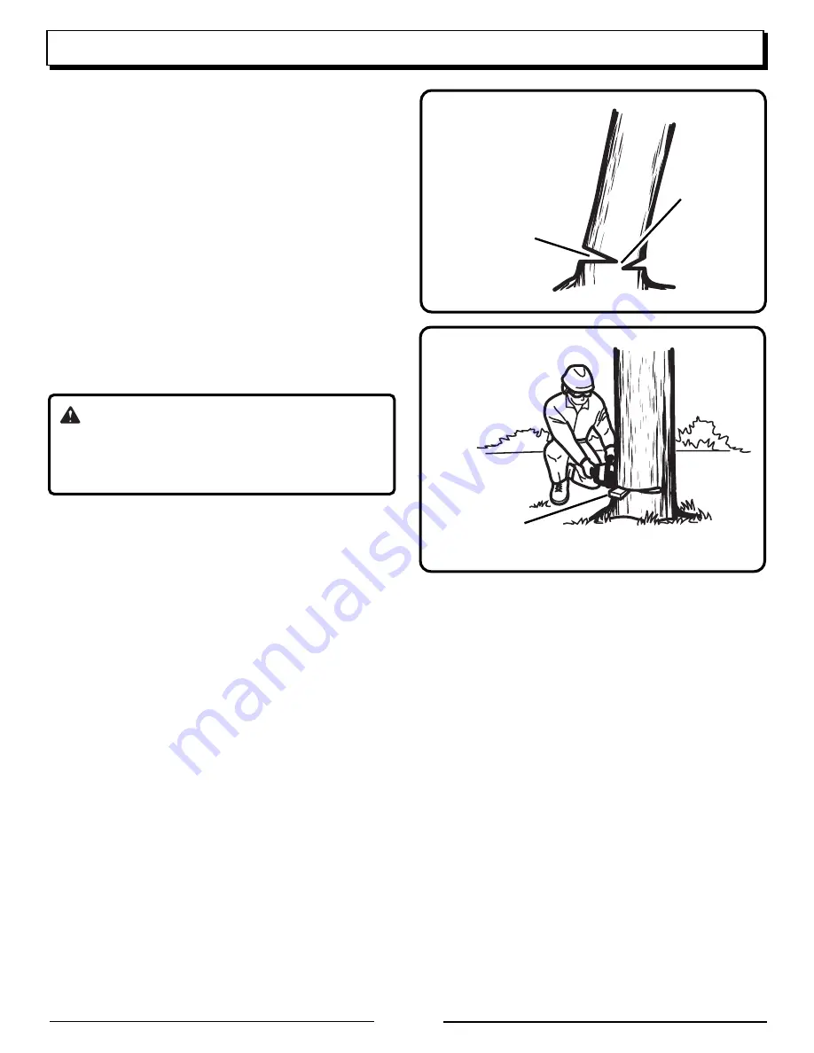
 Never cut through to the notch. Always leave a

band of wood between the notch and back cut (approxi-
mately 2 inches (5 cm) or 1/10 the diameter of the tree).
This is called "hinge" or "hingewood". It controls the fall
of the tree and prevents slipping or twisting or shoot-
back of the tree off the stump.

On large diameter trees, stop the back cut before it is
deep enough for the tree to either fall or settle back on
the stump. Then insert soft wooden or plastic wedges
into the cut so they do not touch the chain. Drive
wedges in, little by little, to help jack the tree over.

When bucking or felling with a wedge, it may be
necessary to remove the SAFE-T-TIP

®

 anti-kickback

device to allow the bar to be drawn through the cut.
After you complete the cut, reinstall the tip immediately.

5.

As tree starts to fall, stop the chain saw and put it down
immediately. Retreat along the cleared path, but watch
the action in case something falls your way.

WARNING:

Never cut through to the notch when making a back
cut. The hinge controls the fall of the tree, this is the
section of wood between the notch and backcut.

HINGE

BACK CUT

WEDGE

Fig. 33

Fig. 32

OPERATION

Summary of Contents for UT10550

Page 1: ...anufactured to Homelite s high standard for dependability ease of operation and operator safety Properly cared for it will give you years of rugged trouble free performance WARNING To reduce the risk of injury the user must read and understand the operator s manual before using this product Thank you for buying a Homelite chain saw SAVE THIS MANUAL FOR FUTURE REFERENCE ...

Page 2: ... years of safe reliable service IMPORTANT Servicing requires extreme care and knowledge and should be performed only by a qualified service technician When servicing use only identical Homelite replacement parts For safe operation read and understand all instructions before using the chain saw Follow all safety instructions Failure to follow all safety instructions listed below may result in serio...

Page 3: ...low the manufacturer s sharpening and maintenance instructions for the saw chain 7 Only use replacement bars and chains specified by the manufacturer or the equivalent DO NOT OPERATE A CHAIN SAW WITH ONE HAND Serious injury to the operator helpers bystanders or any combination of these persons may result from one handed operation A chain saw is intended for two handed use DO NOT OPERATE A CHAIN SA...

Page 4: ...r approved for gasoline Mix fuel outdoors where there are no sparks or flames Select bare ground stop the engine and allow it to cool before refueling Loosen the fuel cap slowly to release pressure and to keep fuel from escaping around the cap Tighten the fuel cap securely after refueling Wipe spilled fuel from the unit Move 30 feet 9 m away from refueling site before starting engine Never attempt...

Page 5: ...G All chain saw service other than items in the operator s manual maintenance instructions should be performed by competent chain saw service personnel If improper tools are used to remove the flywheel or clutch or if an improper tool is used to hold the flywheel in order to remove the clutch structural damage to the flywheel could occur which could subsequently cause the flywheel to burst and ser...

Page 6: ... damage Wear eye hearing and head protection when operating this equipment The SAFE T TIP nose guard on the guide bar helps prevent kickback No smoking sparks or open flame Diagonal line across a symbol means this is prohibited or should be avoided Hold and operate the saw properly with both hands Do not operate the saw using only one hand Engines produce carbon monoxide which is an odorless deadl...

Page 7: ... volume 19 4 oz 575 ml Chain oil tank volume 11 8 oz 350 ml Bar length 18 in 457 mm Chain pitch 325 in 8 3 mm Chain gauge 050 in 1 25 mm Drive sprocket 7 tooth Engine displacement 2 75 cu in 45cc Maximum engine power 2 5HP 1 9KW 9 000 RPM Idle engine speed 2 600 3 400 RPM Fuel tank capacity 19 4 oz 575 ml Oil tank capacity 11 8 oz 350 ml SYMBOLS SPECIFICATIONS UT10570 Weight No bar chain fuel or o...

Page 8: ... FRONT HAND GUARD CHAIN BRAKE FRONT HANDLE CYLINDER COVER TRIGGER RELEASE REAR HANDLE THROTTLE TRIGGER IGNITION SWITCH FUEL CAP CHAIN OIL CAP STARTER FAN HOUSING STARTER GRIP SAFE T TIP PRIMER BULB CHOKE LEVER BAR MOUNTING NUTS ...

Page 9: ... be sure to order one of the Homelite bars listed for your saw in this operator s manual The proper size SAFE T TIP nose guard comes installed on the bar Use only guide bars that have a provision for mounting the SAFE T TIP CHAIN BRAKE See Figures 4 and 5 Chain brakes are designed to quickly stop the chain from rotating When the chain brake lever hand guard is WARNING KICKBACK occurs when the movi...

Page 10: ...act with the eyes wash them immediately with clean water If irritation is still present see a doctor immediately Clean up spilled fuel immediately MIXING THE FUEL This product is powered by a 2 cycle engine and requires pre mixing gasoline and 2 cycle oil Pre mix unleaded gasoline and 2 cycle engine oil in a clean container approved for gasoline This engine is certified to operate on unleaded gaso...

Page 11: ... Fig 9 Fig 10 Fig 8 OPERATING THE CHAIN BRAKE See Figures 10 11 and 12 Refer to Safety earlier in this manual for additional information Check the operating condition of the chain brake prior to each use 1 Using the back of your left hand engage the chain brake by pushing the chain brake lever hand guard toward the bar while the chain is rotating rapidly 2 Reset the chain brake back into the RUN p...

Page 12: ...irmly with the left hand and put your right foot onto the base of the rear handle IGNITION SWITCH IN THE RUN POSITION Fig 14 3 Set the Ignition Switch to the RUN I position 4 Make sure the chain brake is in the RUN position by pulling back on the lever hand guard See Figure 15 5 Fully press and release the PRIMER BULB 7 times 6 Pull CHOKE lever all the way OUT to full position The partial throttle...

Page 13: ...r additional information STOPPING THE ENGINE See Figures 20 and 21 Release the throttle trigger and let the engine return to idle To stop the engine move the Ignition Switch to the O stop position Do not put the chain saw on the ground when the chain is still moving For additional safety set the chain brake when the saw is not in use In the event that the Ignition Switch will not stop the saw pull...

Page 14: ...umb is wrapped under the handlebar This grip is least likely to be broken by a kickback or other sudden reaction of the saw Any grip in which the thumb and fingers are on the same side of the handle is dangerous because a slight kick of the saw can cause loss of control WARNING DO NOT operate the throttle trigger with your left hand and hold the front handle with your right hand Never allow any pa...

Page 15: ...everyone helpers bystanders children and animals a SAFE DISTANCE from the cutting area During felling operations the safe distance should be a least twice the height of the largest trees in the felling area During bucking operations keep a minimum distance of 15 feet 4 5 m between workers ADJUSTING THE CARBURETOR See Figures 26 and 27 Before adjusting the carburetor clean the air filter and the st...

Page 16: ...ue use until the repair is made Serious personal injury may result from the saw chain turning at idle OPERATION STOP Fig 28 FELLING TREES HAZARDOUS CONDITIONS WARNING Do not fell trees during periods of high wind or heavy precipitation Wait until the hazardous weather has ended When felling a tree it is important that you heed the following warnings to prevent possible serious injury Do not cut do...

Page 17: ... to fell a tree along a line different from its natural line of fall 3 Cut a notch about 1 3 the diameter of the trunk in the side of the tree Make the notch cuts so they intersect at a right angle to the line of fall This notch should be cleaned out to leave a straight line To keep the weight of the wood off the saw always make the lower cut of the notch before the upper cut 4 Make the backcut le...

Page 18: ... into the cut so they do not touch the chain Drive wedges in little by little to help jack the tree over When bucking or felling with a wedge it may be necessary to remove the SAFE T TIP anti kickback device to allow the bar to be drawn through the cut After you complete the cut reinstall the tip immediately 5 As tree starts to fall stop the chain saw and put it down immediately Retreat along the ...

Page 19: ...e bar nose and chain during cutting this can cause kickback To avoid the danger keep the SAFE T TIP anti kickback device attached while cutting Refer to Specific Safety Rules Kick back earlier in this manual During bucking operations stand on the uphill side so that the cut off section of the log cannot roll over you Sometimes it is impossible to avoid pinching with just standard cutting technique...

Page 20: ...NG See Figure 38 Begin on the top side of the log with the bottom of the saw against the log exert light pressure downward Note that the saw will tend to pull away from you UNDERBUCKING See Figure 38 Begin on the under side of the log with the top of the saw against the log exert light pressure upward During underbucking the saw will tend to push back at you Be prepared for this reaction and hold ...

Page 21: ...gure 39 1 Underbuck the branch 1 3 through for your first cut 2 Overbuck the branch to drop it 3 Finish by cutting smoothly and neatly against the main member so the bark will grow back to seal the wound WARNING If the limbs to be pruned are above chest height hire a professional to perform the pruning CUTTING SPRINGPOLES See Figure 40 A springpole is any log branch rooted stump or sapling which i...

Page 22: ...ection 1 Always place the Ignition Switch in the stop O position before you work on the saw 2 Make sure the chain brake is not set by pulling the chain brake lever hand guard towards the front handle to the RUN position 3 Wear gloves when handling the chain and bar These components are sharp and may contain burrs 4 Remove the bar mounting nuts using a combination wrench or 5 8 in wrench 5 Remove t...

Page 23: ... are in the long slot of the bar Note for UT10570 When placing the bar on the bar studs ensure that the adjusting pin is in the chain tension pin hole 11 Replace the outer guide bar plate ensuring that the bar pin groove is at the bottom with the upper and lower edges angled away from the guide bar 12 Replace the clutch cover and bar mounting nuts 13 Tighten the bar mounting nuts finger tight only...

Page 24: ...eat this process until sag does not exist 17 Hold the tip of the guide bar up and tighten the bar mounting nuts securely The chain is correctly tensioned when there is no sag on the underside of the guide bar the chain is snug but it can be turned by hand without binding Ensure that the chain brake is not set Note If chain is too tight it will not rotate Loosen the bar nuts slightly and turn the t...

Page 25: ... 25 mm out of the bar groove To help determine the correct warm chain tension use the tip of the combina tion wrench as a guide Note New chain tends to stretch check the chain tension frequently and tension as required CAUTION A chain tensioned while warm may be too tight upon cooling Check the cold tension before next use 050 1 25 mm Fig 54 CHAIN MAINTENANCE See Figures 55 and 56 CAUTION Check th...

Page 26: ... CUTTERS See Figures 57 58 59 60 and 61 Be careful to file all cutters to the specified angles and to the same length as fast cutting can only be obtained when all cutters are uniform 1 Wear gloves for protection 2 Tension the chain prior to sharpening Note Refer to Maintenance Adjusting the Chain Tension earlier in this manual 3 Use a 3 16 in diameter round file and holder Do all of your filing a...

Page 27: ...ngine speed during cutting which may result in severe engine damage WARNING Improper chain sharpening increases the potential of kickback WARNING Failure to replace or repair a damaged chain can cause serious injury WARNING The saw chain is very sharp Always wear protective gloves when performing maintenance to the chain MAINTENANCE ...

Page 28: ...ANGLE LESS THAN 30 Fig 62 30 CORRECT INCORRECT BACKWARD SLOPE SIDE PLATE FILING ANGLE Fig 63 80 CORRECT MAINTAINING DEPTH GAUGE CLEARANCE See Figure 64 65 and 66 Maintain the depth gauge at a clearance of 025 in 0 6 mm Use a depth gauge tool for checking the depth gauge clearances Every time the chain is filed check the depth gauge clearance Use a flat file and a depth gauge jointer to lower all g...

Page 29: ...he guide bar comes with a SAFE T TIP anti kickback device already installed you need to check the tightness of the mounting screw before each use Tighten the mounting screw of the nose guard as in structed below These are specially hardened screws If you cannot install the screw tightly replace both the screw and the SAFE T TIP before further operation Note Do not replace the screw with an ordinar...

Page 30: ...before making any mixture adjustments of the carburetor 1 For access to the air filter and carburetor area loosen the three screws holding the cylinder cover 2 Activate chain brake 3 Lift the front of the cylinder cover past chain brake lever 4 Lift the back of the cylinder cover past the handle 5 Before removing the air filter from the carburetor blow or brush as much loose dirt and sawdust from ...

Page 31: ...damaged REPLACING THE SPARK PLUG See Figure 77 This engine uses a Champion RCJ 4 with 025 in 0 63 mm electrode gap Use an exact replacement and replace every six months or more frequently if necessary 1 Loosen the spark plug by turning it counterclockwise with a wrench 2 Remove the spark plug 3 Hand thread the new spark plug turning it clockwise Note Be careful not to cross thread the spark plug C...

Page 32: ...024 in 60 mm or worn halfway through Always keep the chain brake mechanism clean and lightly lubricate the linkage Always test the chain brake performance after servicing or cleaning Refer to Operation Operating Chain Brake earlier in this manual for additional information Check and if damaged replace the chain catcher STORING THE CHAIN SAW 1 MONTH OR LONGER 1 Drain all fuel from tank into a conta...

Page 33: ...ion pushed in com pletely and pull starter cord 15 to 20 times This will clear excess fuel from engine Clean and reinstall spark plug Set Ignition Switch to run I position Push and fully release primer bulb 7 times Pull starter three times with choke lever at run If engine does not start move choke lever to choke and repeat normal starting procedure If engine still fails to start repeat procedure ...

Page 34: ...saw and check for oil dripping from SAFE T TIP and guide bar If oil is present the chain may be dull or bar may be damaged If no oil is on the SAFE T TIP contact a Homelite Service Center 1 Release chain brake refer to Operation Operat ing Chain Brake earlier in this manual 2 Tension chain per instructions in Maintenance Adjusting the Chain Tension earlier in this manual 3 Refer to Maintenance Ass...

Page 35: ...in respect to claims is limited to making the required repairs or replacements and no claim of breach of warranty shall be cause for cancellation or rescission of the contract of sale of any HOMELITE product Proof of purchase will be required by the dealer to substantiate any warranty claim All warranty work must be performed by an authorized HOMELITE service dealer This warranty is limited to nin...

Page 36: ...m 38cc Chain Saw UT10550 18 in 457 mm 45cc Chain Saw UT10570 20 in 508 mm 45cc Chain Saw For product information technical help dealer locations or parts ordering information visit our website at www homelite com WARNING The engine exhaust from this product contains chemicals known to the State of California to cause cancer birth defects or other reproductive harm CALIFORNIA PROPOSITION 65 983000 ...

Reviews: