background image

48

Restore factory settings

Restore factory settings

The factory settings of the device can be re-
stored. If you do this, you will lose all your set-
tings.

To restore the factory settings of the device, please pro-
ceed as follows:

•  Press and hold down the system button 

(E)

 for 4 

seconds until the LED 

(E)

 starts quickly flashing 

orange (

see fig. 9)

.

•  Release the system button again.
•  Press and hold down the system button again for 

4 seconds, until the LED lights up green (

see fig-

ure 10

).

•  Release the system button to finish the procedure.

The device will perform a restart.


After the restart, you can 

again integrate your device into your system.

Maintenance and cleaning

The product does not require any maintenance. 
Enlist the help of an expert to carry out any re-
pairs.

Clean the device using a soft, lint-free cloth that is clean 
and dry. Do not use any detergents containing solvents, 
as they could corrode the plastic housing and label.

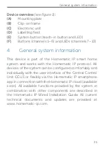
Summary of Contents for IP Wired HmIPW-WRC6

Page 1: ...Installations und Bedienungsanleitung Installating instruction and operating manual Wired Wandtaster 6 fach S 2 Wired Wall mount Remote Control 6 buttons p 29 HmIPW WRC6...

Page 2: ...n oder unter Verwendung elektronischer mechanischer oder chemischer Verfahren verviel f ltigt oder verarbeitet werden Es ist m glich dass die vorliegende Anleitung noch drucktech nische M ngel oder Dr...

Page 3: ...2 1 A B F E C D 1 2...

Page 4: ...4 3 2 1...

Page 5: ...click click 6 5...

Page 6: ...8 7 Homematic Homematic IP Homematic Homematic IP CCU Homematic IP Homematic IP HAP HmIP Ger t anlernen Teach in HmIP device...

Page 7: ...10 9 4 s 4 s...

Page 8: ...4 5 1 Installationshinweise 14 5 2 Installation 16 5 3 Montage in Mehrfachkombinationen 18 5 4 Anlernen 18 5 4 1 Anlernen an die Zentrale CCU3 19 5 4 2 Anlernen an die Homematic IP Cloud per Wired Acc...

Page 9: ...assen bergeben Sie auch diese Anleitung Benutzte Symbole Achtung Hier wird auf eine Gefahr hingewiesen Hinweis Dieser Abschnitt enth lt zus tzliche wichtige Informationen 2 Gefahrenhinweise ffnen Sie...

Page 10: ...ischen Belastungen aus Das Ger t ist kein Spielzeug Erlauben Sie Kindern nicht damit zu spielen Lassen Sie das Verpa ckungsmaterial nicht achtlos liegen Plastikfolien t ten Styroporteile etc k nnen f...

Page 11: ...nicht zul ssig Die not wendige Isolation einer Netzspannung der Haus installation zum Homematic IP Wired Bus ist immer einzuhalten Bei Nichtbeachtung der Ins tallationshinweise k nnen Brand oder ande...

Page 12: ...och bzw runterzufahren oder den Schutzmo dus zu aktivieren deaktiveren Neben jeder der sechs Tasten ist eine Status LEDs integ riert die in sieben verschiedenen Farben leuchten blinken oder pulsieren...

Page 13: ...1 6 und LEDs Kanal 7 13 4 Allgemeine Systeminformationen Dieses Ger t ist Teil des Homematic IP Smart Home Systems und kommuniziert ber das Homematic IP Pro tokoll Sie haben die M glichkeit alle Ger...

Page 14: ...d den Verwendungszweck damit Sie das Ger t im Nachhinein leichter zuordnen k nnen Alter nativ steht die Ger tenummer auch auf dem bei liegenden QR Code Aufkleber Beachten Sie die auf dem Ger t angegeb...

Page 15: ...freiheit feststellen Erden und Kurzschlie en benachbarte unter Spannung stehende Teile abdecken oder abschranken Auswahl des geeigneten Werkzeuges der Messger te und ggf der pers nlichen Schutzausr st...

Page 16: ...schluss des Wired Access Points HmIPW DRAP auf Masse aufgelegt werden Am Wandtaster darf der Schirm nicht aufgelegt werden 5 2 Installation Der Bus wird vom Homematic IP Wired Access Point HmIPW DRAP...

Page 17: ...lieferten Schrauben an der Un terputzdose s Abbildung 4 Setzen Sie den den mitgelieferten Wechselrah men B oder den Rahmen Ihrer vorhandenen Schalterserie auf die Montageplatte auf s Abbil dung 5 6 Le...

Page 18: ...platten Tragringen angebracht und daran ausgerichtet wird Eine bersicht mit den kompatiblen Schalterserien finden Sie im Downloadbereich unter www homematic ip com 5 4 Anlernen Bitte lesen Sie diesen...

Page 19: ...an die Homematic IP Cloud per Wired Access Point auf Seite 22 Dabei ist es m glich die Wired Ger te per Smartphone App ber den Homematic IP Wired Access Point HmIPW DRAP zu steuern oder mit Homematic...

Page 20: ...f Ihrem PC Klicken Sie auf den Button Ger te anlernen im rechten oberen Bereich des Browserfensters Um den Anlernmodus zu aktivieren klicken Sie im n chsten Fenster auf HmIP Ger t anlernen Die Zentral...

Page 21: ...heint das neu angelernte Ger t im Posteingang Ihrer Softwareoberfl che Neu angelernte Ger te und die zugeh rigen Kan le ste hen erst dann f r Bedien und Konfigurationsaufgaben zur Verf gung nachdem si...

Page 22: ...igen Bedienungsanleitung ber die Smartphone App an die Homematic IP Cloud an W hlen Sie den Men punkt Ger t anlernen aus Nach dem Herstellen der Spannungsversorgung ist der Anlernmodus des Ger ts f r...

Page 23: ...Namen f r das Ge r t und ordnen Sie es einem Raum zu Wenn Sie bereits Homematic IP Ger te im Smart Home System nutzen oder Ihre Wired Ger te mit Funk Komponenten von Homematic IP kombi nieren m chten...

Page 24: ...ktionen des Homematic IP Systems gesteuert werden Zus tzlich k nnen die LEDs gew nschte Zust nde anzeigen Legen Sie die Funktionen der Tasten und der LEDs einfach ber die WebUI Benutzeroberfl che oder...

Page 25: ...otes Leuchten Vorgang fehlgeschlagen Versuchen Sie es erneut Kurzes oranges Blinken alle 10 s Anlernmodus aktiv Geben Sie die letzten vier Ziffern der Ger te Seriennummer zur Best tigung ein s 5 4 Anl...

Page 26: ...ie folgt vor Dr cken Sie f r 4 s auf die Systemtaste E bis die LED E schnell orange zu blinken beginnt s Ab bildung 9 Lassen Sie die Systemtaste wieder los Dr cken Sie die Systemtaste erneut f r 4 s b...

Page 27: ...ge h use und die Beschriftung k nnen dadurch angegriffen werden 10 Technische Daten Ger te Kurzbezeichnung HmIPW WRC6 Versorgungsspannung 24 VDC 5 20 SELV Stromaufnahme 40 mA max Leistungsaufnahme im...

Page 28: ...der Richtlinie ber Elektro und Elektronik Altger te ber die rtlichen Sammelstellen f r Elektronik Altger te zu entsorgen Konformit tshinweis Das CE Zeichen ist ein Freiverkehrszeichen das sich aussch...

Page 29: ...on a regular basis and any necessary corrections will be implemented in the next edition We accept no liability for technical or typographical errors or the consequences thereof All trademarks and in...

Page 30: ...instructions 36 5 2 Installation 38 5 3 Installation in multiple combinations 39 5 4 Teaching in 40 5 4 1 Connecting to Homematic IP Central Control Unit CCU3 41 5 4 2 Connecting to the Homematic IP c...

Page 31: ...other persons for use please hand over this manual as well Symbols used Attention This indicates a hazard Note This section contains important additional infor mation 2 Hazard information Do not open...

Page 32: ...children to play with it Do not leave packaging material lying around Plastic films bags pieces of polystyrene etc can be dangerous in the hands of a child We do not assume any liability for damage t...

Page 33: ...t all times Non compli ance with the installation instructions can cause fire or introduce other hazards The device may only be used for fixed installa tions The device must be securely attached with...

Page 34: ...ifferent colours The LEDs can be used to display a wide range of system states such as actual alarm mode switched on lights and open windows The wall mount remote control has a mounting plate to enabl...

Page 35: ...and works with the Homematic IP protocol All devices of the system can be configured comfortably and individually with the user interface of the Central Control Unit CCU3 or flexibly via the Homemati...

Page 36: ...cation purpose in order to make later allocation easier You can also find the device number on the QR code sticker supplied Please note the insulation stripping length of the conductor to be connected...

Page 37: ...ain Check that system is deenergised Earth and short circuit Cover or cordon off neighbouring live parts Select suitable tool measuring equipment and if neces sary personal safety equipment Evaluation...

Page 38: ...GND at the bus connection of the Wired Access Point HmIPW DRAP The shield may not be connected to the wall mount remote control 5 2 Installation The bus is powered by the Homematic IP Wired Access Po...

Page 39: ...r existing switch series on the mounting plate see figure 5 6 Insert the desired labelling template into the la belling field C by removing transparent cover and then replacing it Place the electronic...

Page 40: ...efer to the Homematic IP Wired System Manual for detailed information on setup and control options To integrate the device into your system and enable it to communicate with other devices you must fir...

Page 41: ...evices via the Homematic IP Access Point HmIP HAP 5 4 1 Connecting to Homematic IP Central Control Unit CCU3 To easily operate and configure Homematic IP wired de vices via software as well as use the...

Page 42: ...Teach in HmIP device in the next window The teach in mode of the Central Control Unit will be activated for 60 seconds An information box shows how much teach in time remains After connecting the powe...

Page 43: ...f your software interface Newly connected devices and the corresponding chan nels are ready for operation and configuration only after they have been configured in the inbox You will find fur ther inf...

Page 44: ...ng manual Select the menu item Teach in device After connecting the power supply the device s teach in mode is active for 3 minutes You can manually start the teach in mode for an other 3 minutes by p...

Page 45: ...matic IP devices in your smart home system or if you want to com bine your Homematic IP Wired devices with wire less Homematic IP components you can also connect the Homematic IP Wired devices to an i...

Page 46: ...vices and functions within the Homematic IP system can be operated via the six buttons channels The LEDs can also be used to indicate required states Use the WebUI user interface or the Homematic IP a...

Page 47: ...x long red lighting Operation failed Please try again Short orange flashing every 10 seconds Teach in mode active Please enter the last four numbers of the device serial number to confirm see 5 4 Teac...

Page 48: ...ton again Press and hold down the system button again for 4 seconds until the LED lights up green see fig ure 10 Release the system button to finish the procedure The device will perform a restart Aft...

Page 49: ...umption in standby 45 mW Cable type and cross section Rigid cable 0 12 0 50 mm Installation only in normal commer cial switch boxes device boxes in accordance with DIN 49073 1 Degree of protection IP2...

Page 50: ...d of at local collection points for waste elec tronic equipment in compliance with the Waste Electrical and Electronic Equipment Directive Information about conformity The CE sign is a free trading si...

Page 51: ...Bevollm chtigter des Herstellers Manufacturer s authorised representative eQ 3 AG Maiburger Stra e 29 26789 Leer GERMANY www eQ 3 de...

Reviews: