background image

Operating Instructions

Page 6 of 20

Edition 06, August 2007

Homeplug 8500E Turbo Ethernet Adapter

Installation and Connection

System Requirements

The HomePlug 8500E can be used with all operating systems which support TCP/IP.
Drivers are not required for the HomePlug 8500E. However, the configuration utility
and network password supplied can only be installed on Windows operating
systems.

Your computer must meet the following minimum requirements in order to be able to
install the utility software under Windows.

S

Windows 98SE, Windows Me, Windows 2000 Windows XP or Windows Vista,

S

Network adapter configured for TCP/IP,

S

Pentium III 300 MHz MMX compatible PC or larger,

S

128MB hard disk drive and 128 MB memory (RAM),

S

CD−ROM drive.

Installation and Uninstallation of the Configuration Software

NOTE:  

Only possible with Windows operating systems.

Installation and deinstallation are described for the Windows Vista operating system.
The procedure is the same for all other approved operating systems.

Installation

1. Connect the HomePlug 8500E to your computer or relevant network device

using the network cable.

2. Connect the HomePlug in the power socket.

3. Install the configuration utility (PowerPacket). The Resource CD is provided with

an auto run feature. If this feature fails to run, start the program by
double−clicking on 

Setup.exe

 on the CD.

4. Follow the instructions on the screen to install the software.

NOTE:  

Note down the HomePlug password so that it is available for the

configuration routine.

NOTE:  

If there is no connection/link between the HomePlug installed and network

cable inserted on the HomePlug or the PING test on the HomePlug installed
proves unsuccessful, disconnect the HomePlug, with network cable
connected, from the power socket and install again.

Summary of Contents for 8500E

Page 1: ...Operating Instructions Edition 06 August 2007 Page 1 of 20 Homeplug 8500E Turbo Ethernet Adapter HomePlug 8500E Turbo Ethernet Adapter ...

Page 2: ...ion of the Configuration Software 6 Connection and Control Lamps 7 Application Examples 8 Important Information 11 Network Capacity 11 Network Security 11 Configuration Utility for Windows 12 Starting the Program 12 Main Screen 12 Privacy Screen 15 QoS Screen 16 Diagnostics Screen 17 About Screen 18 Guarantee 19 Technical Modifications 19 Conformity of the HomePlug 8500E to the EU directives is co...

Page 3: ...nected to a mains power outlet whose properties comply to those indicated on the corresponding product labels If there is any cause for doubt consult your dealer or local power company 6 The HomePlug 8500E may only be connected to a fused power outlet Ensure that the fuses and circuit breakers for all the conductive lines are designed for 100 240 V according to the respective national power supply...

Page 4: ...s designed for transmitting data within a power network Any other use is considered unintended use Unauthorised modifications or reconstruction not described in this manual are not permitted Information on Disposal The implementation of European law in national laws and directives obliges you to dispose of consumable goods appropriately This serves to protect both persons and the environment The a...

Page 5: ...cally connected to each other The HomePlug 8500E implements No New Wires communication in every room via any power line at a speed of up to 85 Mbps It has 3 indicator lamps LEDs and a network Ethernet port The LEDs serve to indicate the connection status as well as signalling problems concerning system malfunction The Ethernet port is used to connect the HomePlug 8500E to the network The HomePlug ...

Page 6: ...tion Software NOTE Only possible with Windows operating systems Installation and deinstallation are described for the Windows Vista operating system The procedure is the same for all other approved operating systems Installation 1 Connect the HomePlug 8500E to your computer or relevant network device using the network cable 2 Connect the HomePlug in the power socket 3 Install the configuration uti...

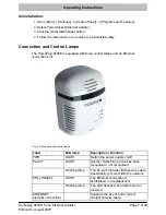
Page 7: ...quipped with three control lamps and an Ethernet connection port Fig 2 Connection and control lamps Label LED lamp Description Function PWR On Off Switch the power supply on off PL ACT On Off Another HomePlug device has been recognised not recognised Flashing lamp The PL ACT indicator flashes when data transmission occurs within the network ETH LINK ACT On Off The Ethernet connection is establishe...

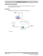
Page 8: ...t Adapter Application Examples The section below illustrates some examples of applications when using the HomePlug 8500E in your network Example 1 Workstation with Internet access via an ADSL cable modem In house power supply HomePlug 8500E HomePlug 8500E ADSL cable modem Fig 3 Example 1 ...

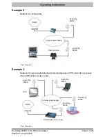
Page 9: ... In house power supply HomePlug 8500E HomePlug 8500E Game console Fig 4 Example 2 Example 3 Network for several workstations with Internet television IPTV and Internet access via an ADSL cable modem router HomePlug 8500E HomePlug 8500E HomePlug 8500E HomePlug 8500E ADSL cable modem router In house power supply IPTV Fig 5 Example 3 ...

Page 10: ...net Adapter Example 4 Network for several workstations with Internet television IPTV and Internet access via an ADSL cable modem and ADSL cable router HomePlug 8500E ADSL cable router In house power supply HomePlug 8500E HomePlug 8500E HomePlug 8500E ADSL Cable modem IPTV Fig 6 Example 4 ...

Page 11: ...overlapping phases If problems arise call an electrician to install a so called phase coupler NOTE In order to use devices from other manufacturers together with the HomePlugs set the same network names and password for all the devices Use the setup utility in this case If necessary refer to the operating manual provided with the device Correct Use of Passwords You can improve your security substa...

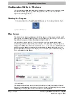
Page 12: ...ich the utility is running If the status of the utility is not updated close the utility and then restart it The top panel Local Device s on your computer displays all the device types concerning devices connected to your computer In most cases only one device is displayed If different devices are available in the network such as a USB device or another Ethernet device for example you can select a...

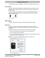
Page 13: ...icons appear beside the device names HomePlug 1 0 HomePlug Turbo Fig 9 Device icons MAC Address The MAC Address column indicates the MAC address of the HomePlug Password The Password column indicates the HomePlug passwords entered Initially no password is displayed The HomePlug passwords are provided on labels on your HomePlugs Proceed as follows to enter the passwords required for private network...

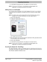
Page 14: ...gs they wish to manage and to add the HomePlugs to the local logical network 1 Click on the Add button 2 A dialog box opens refer to Fig 11 Fig 11 Adding a device to the network 3 Enter the device name in the Device Name input field and the password relevant to the HomePlug in the Password field 4 Click on the OK button 5 A confirmation box appears when the password is entered correctly NOTE If th...

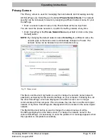
Page 15: ...ePlug to a different name the network type on the Main screen automatically changes to Private The network name can be between 4 and 24 characters long Fig 12 Privacy screen The Set Local Device Only button is used to change the network name network password exclusively for the local HomePlugs on your computer Following this all the other HomePlugs which are displayed on the Main screen can no lon...

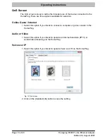
Page 16: ...vailable for selection Online Game Internet 1 Select this option if you intend to connect a computer or game console to the HomePlug Audio or Video 1 Select this option if you intend to operate an Internet television IPTV or Audio Video streaming via the HomePlug Voice over IP 1 Select this option if you intend to operate Voice over IP via the HomePlug Fig 13 QoS screen 2 Click on the Update QoS b...

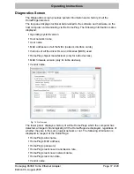
Page 17: ...ork interface cards S Versions of all the driver DLLs and libraries NDIS used S HomePlug chipset manufacturer only for turbo devices S MAC firmware version only for turbo devices S Vendor name Fig 14 QoS screen The lower panel displays a history of all the HomePlugs which the computer has detected arranged chronologically All the HomePlugs are displayed regardless of whether they are in the same l...

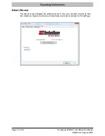
Page 18: ...0 Edition 06 August 2007 Homeplug 8500E Turbo Ethernet Adapter About Screen The About screen displays the software version The user can also choose to click the AutoScan feature to activate or deactivate automatic scanning for HomePlugs ...

Page 19: ...uipment is defective return it together with the purchase receipt and original packaging to the point of sale Technical Modifications This operating instruction manual serves purely for information purposes Its content is not part of any contract of sale All the data relates to nominal values The equipment and options described may differ from country to country according to national requirements ...

Page 20: ...All rights reserved ...
Reviews: