background image

© 1999 American Honda Motor Co., Inc - All Rights Reserved.

 AII 20447 (9908)

9 of 10

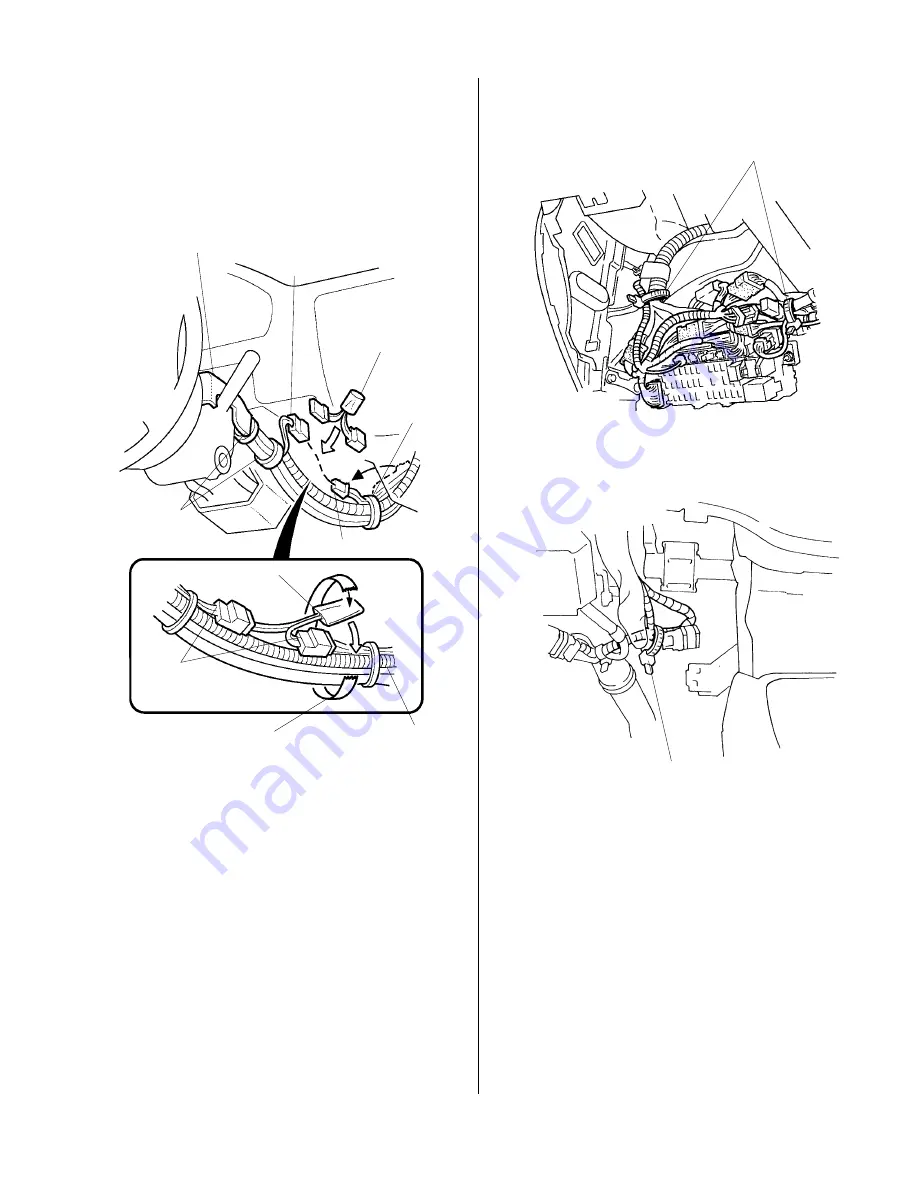
30. Reinstall the upper steering column cover. Locate

the 2-pin connector marked H of the security
harness. Get the resistor supplied with the
attachment kit, plug one end of the resistor into the
2-pin connector marked H and the other end  into the
2-pin connector from the LED.

WIRE TIES

WIRE TIE

31. Tape the resistor to the vehicle harness using

electrical tape. Secure the LED harness to the
vehicle harness with the three short wire ties in the
areas shown.

32. Install the lower steering column cover. Do not pinch

the LED harness with the cover.

33. Attach the security harness to the vehicle harness

with three wire ties in the areas shown.

UPPER
STEERING
COLUMN COVER

VEHICLE
HARNESS

SHORT
WIRE TIES

ELECTRICAL
TAPE

2-PIN
CONNECTOR

RESISTOR

SHORT
WIRE TIE

2-PIN CONNECTOR
(MARKED H)

RESISTOR

LED 2-PIN
CONNECTOR

Summary of Contents for 08E55-S01-100H

Page 1: ... sold separately P N 08E51 S01 101F SECURITY SYSTEM Security Harness sold separately P N08E55 S01 101 AUG 1999 2000 CIVIC 2 3 4 DOOR DX CX MODELS ONLY Owner sManual discard 2Washer screws not used Relay 4 pin Relay 5 pin 2 Fuses 3A not used 2 Long wire ties not used Card not used 2 Decals Fuse box cover not used Control unit Security harness 5 Wire ties AII 20447 Cushion tape Fuse label Y0540 B ...

Page 2: ...ut Washer Owner sManual Cushion tape 2 Collars Flange bolt 6 x 12 mm 2 Bolts 4 x 30 mm Wire tie 4 Short wire ties white TOOLS AND SUPPLIES REQUIRED Phillips screwdriver Stubby Phillips screwdriver Drill 5 5 mm and 12 mm Drill bits Tape measure 10 mm and 12 mm Sockets Ratchet 7 mm 10 mm 12 mm and 17 mm Combination wrenches Diagonal cutters Utility knife Electrical tape Control unit bracket Resistor...

Page 3: ...r the preset buttons 2 Disconnect the negative cable from the battery 3 Move the switch on the control unit into the correct mode for the CX and DX models Customer Information The information in this installation instruction is intended for use only by skilled technicians who have the proper tools equipment and training to correctly and safely add equipment to your car These procedures should not ...

Page 4: ...ft kick panel two clips and slide back while pulling its lower end inside 7 Remove the upper steering column cover three screws and six clips Installing the LED 8 Measure and mark the upper steering column cover removed in step 7 and lightly center punch the mark 9 While wearing eye protection drill a 5 5 mm hole through the center punched mark Remove all burrs 10 Route the terminal ends of the LE...

Page 5: ...PIN CONNECTOR WHITE WIRE RED WIRE Insert the tabs into the grooves slide the lock toward the front and press down on the end Firmly push the terminal into the connector until they click into position Installing the Disarm Switch 20 mm 14 mm 12 mm DRILL BIT DASHBOARD LOWER COVER 12 mm NUT WASHER PREDRILLED HOLE DASHBOARD LOWER COVER DISARM SWITCH Firmly push the terminal into the connector until th...

Page 6: ...mm bolts 19 Cut the cushion tape in two and attach the pieces to the bracket of the steering shaft CONTROL BRACKET INTERLOCK CONTROL UNIT A T only EXISTING BOLT Reuse on A T model vehicle 6 x 12 mm FLANGE BOLT supplied HOLE CONTROL BRACKET SLOT VEHICLE BOLT Reuse on A T model vehicle CONTROL UNIT COLLARS 4 x 30 mm BOLTS BRACKET CUSHION TAPE 16 Loosen the bolt on the right of the steering shaft the...

Page 7: ... LABEL 3A ELECTRICAL TAPE ELECTRICAL TAPE VEHICLE HARNESS WIRE TIE Branch position of security harness SECURITY HARNESS 24 Attach the security harness to the vehicle harness with one wire tie in the area shown LIGHT SWITCH SECURITY HARNESS VEHICLE 7 PIN CONNECTOR WIRE TIE SECURITY HARNESS 21 Connect the 4 pin relay and the 6 pin relay to the security harness connectors then secure them to the secu...

Page 8: ...he 7 pin connector brown from the top of the fuse box and plug the connectors marked C of the security harness in between VEHICLE 16 PIN CONNECTOR BLUE VEHICLE 5 PIN CONNECTOR BROWN SECURITY HARNESS VEHICLE 7 PIN CONNECTOR BROWN SECURITY HARNESS 7 PIN CONNECTOR MARKED C STEERING HANGER BEAM VEHICLE 6 PIN CONNECTOR GRAY No 5 CONTROL UNIT SECURITY HARNESS 22 PIN CONNECTOR 28 Plug the connector marke...

Page 9: ...om the LED WIRE TIES WIRE TIE 31 Tape the resistor to the vehicle harness using electrical tape Secure the LED harness to the vehicle harness with the three short wire ties in the areas shown 32 Install the lower steering column cover Do not pinch the LED harness with the cover 33 Attach the security harness to the vehicle harness with three wire ties in the areas shown UPPER STEERING COLUMN COVER...

Page 10: ...s are plugged in 37 Reinstall all removed parts 38 Connect the negative cable to the battery 39 Check operation of the Security System according to its Owner s Manual supplied with the Security Attachment 40 For ContinuouslyVariableTransmission CVT only perform the start clutch calibration procedure according to the Service Manual whenever the battery is disconnected of the battery backup fuse is ...

Reviews: