background image

2 of 7

AII 23619 (0205)

© 2002 American Honda Motor Co., Inc - All Rights Reserved.

INSTALLATION

Customer Information: The information in this
installation instruction is intended for use only by
skilled technicians who have the proper tools,
equipment, and training to correctly and safely add
equipment to your vehicle. These procedures
should not be attempted by “do-it-yourselfers.”

1.

Make sure you have the anti-theft code for the
radio, then write down the frequencies for the
preset buttons.

2.

Disconnect the negative cable from the battery.

3.

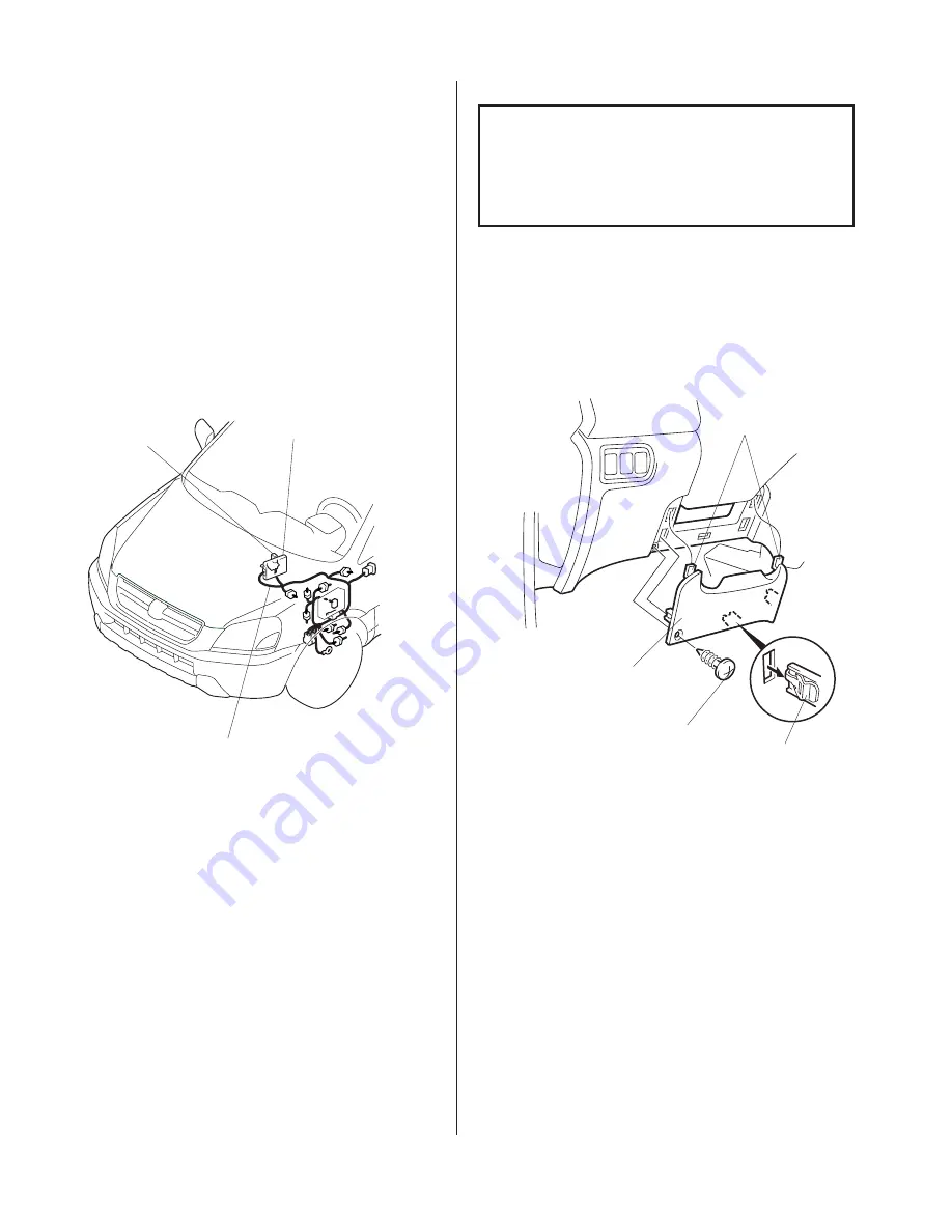
Remove the driver’s dashboard lower cover (one
self-tapping screw, three clips, and two hooks).

TOOLS AND SUPPLIES REQUIRED

Phillips screwdriver

Flat-tip screwdriver

8 mm and 10 mm Combination wrenches

Ratchet

10 mm and 12 mm Sockets

Torque wrench

Diagonal cutters

Isopropyl alcohol

Shop towel

Scissors

Illustration of Keyless Entry Installed on the
Vehicle

RELAY

CONTROL UNIT

KEYLESS ENTRY HARNESS

HOOK

DRIVER’S
DASHBOARD
LOWER COVER

CLIPS (3)

SELF-TAPPING
SCREW

Summary of Contents for 08E61-S84-100

Page 1: ...000 91 KEYLESS ENTRY SYSTEM PARTS LIST Keyless Entry Kit P N 08E61 S84 100 Keyless entry harness Unit bracket 2 Flange nuts 8 Wire ties Relay Fuse label 2 Wire ties with clip 2 Cushion tapes Ground bolt MAY 2002 AII 23619 PILOT 2 Remote controls Control unit Owner s Manual 2 Washer screws 4 x 30 mm Attachment Kit P N 08E65 S9V 100 http www HandA Accessories com ...

Page 2: ...he anti theft code for the radio then write down the frequencies for the preset buttons 2 Disconnect the negative cable from the battery 3 Remove the driver s dashboard lower cover one self tapping screw three clips and two hooks TOOLS AND SUPPLIES REQUIRED Phillips screwdriver Flat tip screwdriver 8 mm and 10 mm Combination wrenches Ratchet 10 mm and 12 mm Sockets Torque wrench Diagonal cutters I...

Page 3: ...ness connector from the switch INTERIOR LIGHT HARNESS CONNECTOR RETAINING TAB SWITCH TRIM INTERIOR LIGHT SWITCH CLIPS 2 RETAINING TABS 2 FUEL LID OPENER KNOB LEFT FRONT TRIM CLIPS 2 CLIP CLIP LEFT KICK PANEL WEATHERSTRIP CLIP 4 x 30 mm WASHER SCREW CONTROL UNIT UNIT BRACKET FLANGE NUT 8 Position the unit bracket on the control unit and install the two 4 x 30 mm washer screws and two flange nuts 7 ...

Page 4: ...of the wire tie into the hole in the unit bracket CONTROL UNIT HOLE WIRE TIE WITH CLIP KEYLESS ENTRY HARNESS KEYLESS ENTRY HARNESS 22 PIN CONNECTOR 50 mm UNIT BRACKET STEERING HANGER BEAM BRACKET BOLT Reuse 14 Remove the bolt that secures the front of the steering hanger beam bracket then attach the unit bracket with this bolt Torque the bolt to 19 to 24 N m 14 to 18 lb ft 13 Attach the other wire...

Page 5: ...ind a gray 4 pin connector Pull the gray 4 pin connector down and out of the clip on the instrument panel bracket Remove the blue tape securing the gray 2 pin connector and pull it out 19 Below the fuse box locate the brown 2 pin connector Plug the keyless entry harness 2 pin connectors into the brown connector and into the gray 2 pin connector from step 18 Reinstall the gray 4 pin connector KEYLE...

Page 6: ...1 pin connectors you just unplugged Reinstall the vehicle 1 pin connector 20 Open the fuse case covers and check the rating of each fuse Attach the fuse labels OPTION 5 A 2 A to the fuse cases on the keyless entry harness KEYLESS ENTRY HARNESS KEYLESS ENTRY HARNESS FUSE CASE HOOD OPENER LEVER FUSE LABEL 2 A GROUND BOLT Provided VEHICLE BOLT Discard FUSE LABEL 5 A KEYLESS ENTRY HARNESS FUSE CASE KE...

Page 7: ...nnected the driver s window AUTO function is disabled 34 Start the engine Push down on the driver s window switch until the window is fully open 35 Pull up on the driver s window switch to close the window completely then hold the switch for 2 seconds 36 Lower and raise the driver s window to check operation of the driver s window AUTO function 37 Do the PCM idle learn procedure Make sure all elec...

Reviews: