background image

Summary of Contents for 2005 CRF450R

Page 1: ......

Page 2: ...J ...

Page 3: ...nd the safety of others Is very impol1an1 To help you ma e informed decisions we haWl provided safety messages and other information throughout this manual Of course il is not practical or poSSible to warn you about all the hazards associated with servicing this I hicle You must use your own good judgement You will find important safety Information In a ariety 01 torms induding Safety Labels on th...

Page 4: ...bdenum disulfide grease containing more than 3 molybdenum disulfide NLGI 2 or equivalent Example Moly oteJ l BR 2 plus manufactured by Dow Corning U S A Multi purpose M 2 manufactured by Milsubishi Oil Japan Use molybdenum disulfide paste containing more than 40 molybdenum disulfide NLGI 2 or equivalent Example Molykote G n Paste manufactured by Dow Corning U S A Honda Moly 60 U S A only Rocol ASP...

Page 5: ...FICATIONS OS 07 1 9 CRANKCASE CRANKSHAFT TRANSMISSION BALANCER SPECIFICATIONS IAfter 07 1 10 FRONT WHEEL SUSPENSION STEERING SPECIFICATIONS 1 11 REAR WHEEL SUSPENSION SPECIFICATIONS 1 11 HYDRAULIC BRAKE SPECIFICATIONS 1 12 BATTERY CHARGING SYSTEM SPECIFICATIONS 1 12 IGNITION SYSTEM SPECIFICATIONS 1 12 ELECTRIC STARTER SPECIFICATION 1 13 LIGHTS METER SWITCHES SPECIFICATIONS 1 13 STANDARD TORQUE VAL...

Page 6: ...th English fastener 4 Install new gaskets O rings cotter pins and lock plates when reassembling 5 When tightening bolts or nuts begin with the larger diameter or inner bolt first Then tighten to the specified torque diagonally in incremental steps unless a particular sequence is specified 6 Clean parts in cleaning solvent upon disassembly lubricate any sliding surfaces before reassembly 7 After re...

Page 7: ...INFORMATION The engine serial number is stamped on the left side of the lower crankcase The carburetor identification number is stamped on the left side of the carburetor body The name plate U S A or Safety Certification Label Canada is attached on the right side of the frame ENGINE SERIAL NUMBER 1 3 ...

Page 8: ...r 05 06 California type 07 U S A fender 05 06 California type 07 U S A DO EMISSION CDNTROllNFORMATION LABEL The Vehicle Emission Control Information label is attached on the rear After 07 U S A and Canada fender After 07 U S A and Canada ada type only V EMISSION CONTRO NFORMATION LABEL 1 4 ...

Page 9: ... disc Rear brake swept area 391 1 cm 60 6 1n2 Caster angle 05 07 27 10 After 07 27 03 Trail length 05 07 110 mm 4 3 in After 07 114 7 mm 4 52 in Fuel tank capacity 05 07 8 6 liter 2 27 US gal 1 89 Imp gal After 07 7 2 liter 1 90 US gal 1 58 Imp gal Fuel tank reserve capacity 05 07 1 4 liter 0 37 US gal 0 31 Imp gat After 07 1 6 liter 0 42 US gal 0 35 Imp gat ENGINE Bore and s1roke 96 0 x 62 1 mm 3...

Page 10: ... 51 13 Gear ratio 2 230 29 13 2nd 1 625 26116 3 d 1 235 21 17 th lOOO 19119 5th 0 826 19123 Gearshift panern Left foot operated return system l N 2 3 4 5 ELECTRICAL Ignition system leM Ignition Control Module Starting system Electric starter motor and kickstarter Charging system Single phase output alternator Regulator rectifier SeR shorted Single phase half wave rectification lighting system Alte...

Page 11: ...Canada or equivalent motor i API seNice classification SG or Higher JASO T 903 standard MA SAE lOW 3D SPECIFICATIONS 8 6 liter 2 27 US gal 1 89 Imp gal 7 2 liter 1 90 US gal 1 58 Imp gal FCR04A FCR13A FCR13B 142 145 45 NCVU NHTU NNEU 2nd position from the top Fixed position 114 turns out 1 1 8 turns out 8 0 rnm 0 31 in 1 700 100 rpm 3 5mm 1 8 3116in 2 3 mm 1 116 118 in 56 kPa 420 mmHg 4 6 kO COOLI...

Page 12: ...GENERAL INFORMATION CYLINDER HEADIVALVES SPECIFICATIONS valve guide EX 17 9 18 1 0 70 0 71 I CYLINDER PISTON SPECIFICATIONS Top 0 065 O lOa 0 0026 0 0039 0 15 0 0045 0 20 0 70 0 008 0 028 0 90 0 035 1 8 ...

Page 13: ...CLUTCH STARTER CLUTCH KICKSTARTER GEARSHIFT LINKAGE SPECIFICATIONS gear gear gear CRANKCASE CRANKSHAFT TRANSMISSION BALANCER SPECIFICATIONS 05 07 i i clearance C2 0 020 0 062 0 0008 0 0024 fork shaft Unit mm 0 12 0 005 1 9 ...

Page 14: ...GENERAL INFORMATION CRANKCASE CRANKSHAFT TRANSMISSION BALANCER SPECIFICATIONS After 07 fork 1 10 clearance M5 C2 C3 0 020 0 062 D OOOS 0 0024 I Unit mm I I 0 12 0 005 ...

Page 15: ...RMATION FRONT WHEEL SUSPENSION STEERING SPECIFICATIONS 0 0 After i 9 clicks out from full in REAR WHEEl SUSPENSION SPECIFICATIONS i I absorber 20 0 24 0 kgf 44 1 52 9 Ibf j j I i 10 clicks oul from full in j j 1 11 ...

Page 16: ...NERAL INFORMATION HYDRAULIC BRAKE SPECIFICATIONS Fi m R79 6mm 3 13 in BATTERYICHARGING SYSTEM SPECIFICATIONS i cur IGNITION SYSTEM SPECIFICATIONS I resistance at 20 CJ68 F I I I I 1 12 Below 12 4 V 4 SkO ...

Page 17: ...ATION ELECTRIC STARTER SPECIFICATION ITEM Starter motor brush length STANDARD 10 25 0 404 LIGHTS METER SWITCHES SPECIFICATIONS ITEM SPECIFICATIONS Headlight 12V 35W Tail light L ED Fuse 15 A SERVICE UMIT 6 75 0 266 1 13 ...

Page 18: ... screw replace with new one 6 Loosen the bolt 118 to 1 4 turns after tightening it to the specified torque then tighten the pivot nut 7 Apply grease to the threads 8 uas nut 9 After 07 Apply molybdenum disulfide grease T81901 or equivalent to the threads lO Apply Honda Hondalock 3 or equivalent high strength locking agent to the threads ENGINE MAINTENANCE Engine oil drain bolt ITEM Transmission oi...

Page 19: ...NGINE REMOVAl INSTALLATION ITEM OTI THREAD TORQUE REMARKS DIA lmmJ N m kgf m Ibf tt Drive sprocket bolt 1 8 31 3 2 23 CYLINDER HEADIVALVES ITEM O TV THREAD TORQUE REMARKS DIA lmm N m kgf m Ibf ftJ Cylinder head cover bolt 3 6 10 1 0 7 Camshaft holder mounting bolt 4 6 14 1 4 10 NOTE 1 Decompressor lifter arm mounting ou1 05 07 1 8 22 2 2 16 NOTE 1 Decompressor cam mounting bolt 05 07 8 24 2 4 18 N...

Page 20: ...7 NOTE 10 screw After 07 2 6 20 2 0 15 NOTE 10 Countershaft bearing set plate screw 2 6 10 1 0 7 NOTE 2 Gearshift drum bearing set plate bolt 2 6 10 l O 7 NOTE 2 Mainshaft bearing set plate bolt 2 6 10 1 0 7 NOTE 2 Balancer shaft bearing set plate bolt 2 6 10 to 7 NOTE 2 Balancer shaft nut 1 14 44 4 5 32 NOTE 1 Cam chain tensioner bolt 1 6 12 1 2 9 NOTE 2 IGNITION SYSTEM ITEM a TV THREAD TORQUE RE...

Page 21: ...buretor side After 07 Carburetor side Cylinder head side insulator band After 07 Cylinder stud bolt Water hose clamp 2 g ci 0 M n E E GENERAL INFORMATION 12 0 1 0 mm 0 47 0 04 in 9 0 1 0 mm 0 35 0 04 in w m in KTi 3 3 0 0 t0 1 0 mm 0 0 04 in 1 17 ...

Page 22: ... 5 ll0 l 8 Radiator shroud upper mounting bolt 4 5 5 0 5 3 7 Rear fender mounting bolt 4 6 13 1 3 10 MAINTENANCE ITEM a TV THREAD TORQUE REMARKS OlA mm N m kgf m Ibf ft Sidestand pivot bolt 1 10 See page 4 34 NOTE 6 Sidestand pivot nut 1 10 39 4 0 29 NOTE 4 Throttle cable adjuster lock throttle side 1 7 4 0 4 3 0 nut carburetor side 1 6 4 10 4 3 0 Spark arrester mounting bolt 05 07 4 6 12 1 2 9 Af...

Page 23: ...nle side 1 6 4 0 4 3 0 Tripmeter cable clamp screw 2 4 0 7 0 1 0 5 Steering damper mounting bolt After 07 2 7 20 2 0 15 NOTE 2 REAR WHEEL SUSPENSION ITEM a TY THREAD TORQUE REMARKS DIA mmJ N m kgf m IbUt Rear axle nut 1 22 128 13 1 94 NOTE 4 Rear spoke 32 4 5 3 7 0 4 2 7 Rear rim lock 1 8 12 1 2 9 Rear brake disc nut 6 6 16 1 6 12 NOTE 4 Driven sprocket nut 6 8 32 3 3 24 NOTE 4 Rear wheel bearing ...

Page 24: ... bolt 2 6 13 1 3 10 Rear master cylinder reservoir cover bolt 2 4 1 0 0 1 0 7 Front caliper pin bolt 1 8 22 2 2 16 NOTE 2 Rear caliper pin bolt 1 12 27 2 8 20 Brake caliper pad pin 2 10 18 1 8 13 Front brake caliper pad pin plug 1 10 2 0 2 1 5 Front caliper bracket pin bolt 1 8 22 2 2 16 NOTE 2 Rear caliper bracket pin bolt 1 8 12 1 2 9 NOTE 2 Brake pedal pivot bolt 1 10 36 3 7 27 NOTE 7 Brake ped...

Page 25: ...and piston pin hole Piston pin outer surface Piston rings Cylinder bore Decompressor cam mounting bolt threads 05 07 Decompressor lifter arm mounting nut threads and seating surface 05 07 Decompressor adjuster lock nut threads OS 07 Clutch lifter and lifter rod sliding area Clutch lifter piece needle bearing Clutch disc linings and plates Clutch center lock nut threads and seating surface Clutch o...

Page 26: ...w threads Throttle shaft torx screw threads Oil jet mounting bolt threads Crankcase tightening bolt threads 05 06 After 06 Crankshaft bearing set plate torx screw threads Alternator wire grommet sealing surface 1 22 MATERIAL Multi purpose grease locking agent l ocking agent Pro Honda Hondalock 3 or equivalent high strength locking agent liquid sealant REMARKS Coating width 4 5 1 0 mm 0 18 0 04 in ...

Page 27: ...in bolt sliding area Silicone grease Brake caliper bracket pin bolt sliding area Brake caliper dust seal lips Brake caliper and bracket pin boots inside surface Brake lever pivot bolt sliding suriace Brake lever adjuster tip Rear master cylinder push rod rounded surface Rear master cylinder boot fitting area Drive chain slider screw threads Locking agent Fork protector mounting bolt threads Front ...

Page 28: ...L REMARKS Front engine hanger la engine contacting area Molybdenum disulfide paste Dow Corning 321 or equivalent Diffuser 1 05 07 Sealant Spark arrester mounting bolt threads After 07 Molybdenum disulfide grease TBl901 or equiva lent 1 24 ...

Page 29: ...LE STARTER SWITCH WIRE ENGINE STOP BUTTON WIRE THROTTLE CABLES FRelNT BRAKE HOSE TRIPMETER CABLE J WIRE HARNESS ENGINE STOP BUTTON CLUTCH SWITCH 3P BLACK CONNECTOR HE DLIG 1T3P BLUE CONNECTOR CLUTCH CABLE THROTTLE CABLES HOT STAAT CABLE 1 STARTER SWITCH WIRE ENGINE STOP BUTTON WIRE FUEL TANK BREATHER HOSE 1 25 ...

Page 30: ...ORMATION THAonlE CABLES CLUTCH CABLE SIPHON HOSE OVERFLOW HOSE FRONT BRAKE HOSE 1 26 TAIPMETER CABLE HOT START CABLE ENGINE STOP BunON WIRE IGNITION PULSE GENERATOR 2P BLACK CONNECTOR ALTERNATOR 4P BLACK CONNECTOR ...

Page 31: ... RADIATOR SIPHON HOSE RADIATOR OVERFLOW HOSE ALTERNATOR WIRE o HOSE AlA VENT HOSES o GENERAL INFORMATION CARBURETOR OVERFlOWI DRAIN HOSE CRANKCASE BREATHER HOSE BRAKE HOSE 1 27 ...

Page 32: ... CRANKCASE BREATHER HOSE 05 and 06 California type 07 SPARK PLUG WIRE HOT STAAT CABLE MAIN WIRE HARNESS THROTIlE POSITION SENSOR CONNECTOR 1 28 CRANKCASE BREATHER HOSE SIPHON HOSE THROTTl_E CABLES CLUTCH CABLE RADIATOR HOSES TRANSMISSION BREATHER HOSE THROTIlE CABLES CLUTCH CABLE PAIR AIR SUCTION HOSE TRANSMISSION BREATHER HOSE ...

Page 33: ...THER HOSES fi i 41 f1 AIR VENT HOSES ALTERNATOR WIRE CRANKCASE BREATHER HOSE o GENERAL INFORMATION VUTCHCABLE TRANSMISSION BREATHER HOSES CARBURETOR OVERFLOWI DRAIN HOSE PAIR AIR SUCTION HOSE AIR VENT HOSES CLUTCH CABLE i rn o TRANSMISSION r BREATHER HOSES CARBURETOR OVERFLOWI DRAIN HOSE 1 29 ...

Page 34: ...GENERAL INFORMATION BATIERY MAIN WIRE HARNESS WIRE 1 30 BATIERY NEGATIVE H CABLE TAil I ____leM 6P NATURAL 1 7 CONNECTOR STARTER RELAY SWITCH IGNITION CONTROL MODULE oeM leM 6P BROWN CONNECTOR ...

Page 35: ...NERAL INFORMATION SECONDARY AIR SUPPLY SYSTEM 05 and 06 California type 07 CRANKCASE BREATHER HOSES TRANSMISSION BREATHER HOSES PAIR AIR SUCTION HOSE AIR SUPPLY PIPE PAIR CONTROL VALVE AIR SUPPLY HOSE 1 31 ...

Page 36: ...BLES TRIPMETER CAl HOT CABLE ENGINE BUTTON WIRE 20 0 8 in li ffl _ 1 32 CABLE CLUTCH CABLE HOT START CABLE ENGINE STOP BUTTON WIRE ENGINE STOP BUTTON CLUTCH t SWITCH 3P BLACK CONNECTOR STARTER SWITCH 2P BLACK CONNECTOR I WIRE HARNESS HEADLIGHT 3P NATURAL CONNECTOR THROTTLE CABLES FUEL BREATHER HOSE ...

Page 37: ...THROTTLE CABLES ENGINE STOP BUTTONI CLUTCH SWITCH 3P BLACK CONNECTOR CLUTCH S ITIC WII F CONNECTOR FRONT HOSE SIPHON HOSE GENERAL INFORMATION r CABLE START CABLE ENG IE STOP BUnONWIRE 1 33 ...

Page 38: ... INFORMATION RADIATOR SIPHON HOSE IGNITION PULSE GENERATOR 2P BLACK CDNNECTOR ALTERNATOR4P BLACK CQNNECTOR HOT START CABLE RADIATOR OVI ERF lO W 1 34 0 3 mm O O 1 in J CRANKCASE P BREATHER HOSE REAR BRAKE HOSE ...

Page 39: ...L INFORMATION THAOTILE CABLES CLUTCH CABLE RA JlAlrOR HOSES PAIR SUCTION HOSE CRANKCASE BREATHER HOSE TR N 5MISSION BREATHER HOSE CRANKCASE BREATHER HOSES j VF m AIR VENT HOSES ALTERNATOR WIRE CRANKCASE BREATHER HOSE PAIR AIR SUCTION HOSE f q il i 7A1R VENT HOSES CLUTCH CABLE TRANSMISSION k l BREATHER HOSES CARBURETOR OVERFLOW DRAIN HOSE 1 35 ...

Page 40: ...LE leM 6P NATURAL CONNECTOR ST RllER RELAY SWITCH IGNITION CONTROL MOOUlE lCM REIGULAlrOFVR Cl 1F1 III R WIRE CRANKCASE BREATHER HOSE PAIR AIR SUCTION HOSE TRANSMISSION BREATHER HOSES 1 36 AIR leM 6P BROWN CONNECTOR CRANKCASE BREATHER HOSE COINTflOLVALVE AIR HOSE Y PIPE ...

Page 41: ...anner Pin spanner A j 2 For shock absorber spring installed length preload adjustment two required Air gauge DRIVE CHAIN SPROCKET Driven sprocket chain link Standard 51T Aluminum 1114 Optional 50T Aluminum 114 52T Aluminum 116 HANDLEBAR LOWER HOLDER Standard 3 mm offset Optional no offset 1 37 ...

Page 42: ... 10 9 Imp oz FORK After 07 Spring TYPE SPRING RATE OIL CAPACITY light 2 scribe marks 0 45 kgf mm Standard 0 25 20 Ibt in 330 eml 11 2 US OZ 11 6 Imp oz Maximum 407 cml 13 8 US OZ 14 3 Imp oz Minimum 311 cm3 10 5 US OZ 10 9 Imp oz Standard No mar factory 0 47 kgf mm Standard 0 products or 1 scribe 26 32 Ibflin 324 cm3 11 0 US OZ 11 4 Imp oz mark aher market Maximum parts 402 cm 13 6 US OZ 14 2 Imp ...

Page 43: ...paint after pans Silver paint The standard shock spring mounted on the motorcycle when it leaves the factory is not marked Before replacing the spring be sure to mark it so it can be distinguished from other optional springs 1 39 ...

Page 44: ...n monoxide does not react in the sarna way but is toxic Honda Motor Co Ltd utilizes appropriate carburetor settings as well as other systems to reduce carbon monoxide and hydrocarbons EXHAUST EMISSION CONTROL SYSTEM The exhaust emission control system is composed of lean carburetor setting no adjustments should be made except for high altitude setting and idle speed adjustment with the throttle st...

Page 45: ...intake manifold vacuum and will cut off the supply of fresh air during r engine deceleration thereby preventing aherburn in the exhaust system No adjustment to the PAIR system should be made although periodic inspection of the components is recommended PAIR COIN lOLVALVE AIR HOSE SERVICING THE HONDA U S A Only VACUUM HOSE AIR CLEANIER J FRESH AIR EXHAUST GAS VACUUM AlA Maintenance replacement or r...

Page 46: ...ehicle or parts of the exhaust or intake system with parts other than those specified by the manufacturer FUEL PERMEATION EMISSION CONTROL SYSTEM After 07 This motorcycle complies with the Fuel Permeation Emission Control regulations of the U S Environmental Protection Agency EPA the California Air Resources Board CARB and Environment Canada The fuel tank fuel hoses and fuel vapor charge hoses use...

Page 47: ...2 TECHNICAL FEATURE AUTO DECOMPRESSION SYSTEM After 07 2 2 HPSD Honda Progressive Steering Damper After 07 2 3 c 2 1 ...

Page 48: ...des from the exhaust cam lobe and depresses the exhaust valve via the rocker arm The exhaust valve is slightly opened end releases some cylinder compression for easy starting AFTER THE ENGINE STARTS After the engine starts the decompressor weight moves outward by centrifugal force The decompressor weight turns pin A on the decompressor shaft Pin 8 on the decompressor shaft turns with the decompres...

Page 49: ...be adjusted with the adjuster piece by turning the plug bott The adjuster piece adjusts the damping force of both compression and extension Turning the plug bolt clockwise will increase damping force and turning it counterclockwise will decrease damping force Free piston Reservoir Spring When compressing the damper rod damper oil moves temporarily into the reservoir The damper oil stored in the re...

Page 50: ...gle B Stroke when angle A When the steering is in the neutral position HPSD generates no damping force and has no effect on steering torque The steering torque differs between the extension and compression of the damper rod The required damping force is controlled w hen the damper piston travels across the groove in the damper case The required steering torque differs between high and low damper r...

Page 51: ...d adjuster piece in the damper case Hard c 0 c cr B a c c 0 0 ti 0 E 0 u Hard High damper rod speed Low damper rod speed Full Steering angle a When the damper rod is extended across the groove Damping force is controlled when the oil flows through the groove in the damper case Hard c 0 c cr B a c c 0 0 E 0 u Hard High damper rod speed Low damper rod speed Q 7 Full _ a Steering angle ADJUSTER PIECE...

Page 52: ...e damper case Hard c a c S 0 c c 0 a a E a 0 Hard High damper rod speed Low damper rod speed Full Steering angle 0 When the damper rod is compressed outside of the groove GROOVE Damping force is generated when the oil flows through the valves and adjuster piece in the damper case Hard c a c a 0 c c 0 a 3l a E a 0 Hard 2 6 High damper rod speed l ow damper rod speed G Full Steering angle ADJUSTER P...

Page 53: ...AME BODY PANELS EXHAUST SYSTEM SERVICE INFORMATION 3 2 ENGINE GUARD 3 5 TROUBLESHOOTING 3 2 FRONT VISOR 3 5 SEAT 3 3 SUB FRAME 3 6 SIDE COVER 3 3 FUEL TANK 3 8 RADIATOR SHROUD 3 4 EXHAUST SYSTEM 3 9 l l 3 1 ...

Page 54: ...ing bolt Sub frame upper mounting bolt Sub frame lower mounting bolt Sub frame upper lower mounting bolt Exhaust pipe joint nut Muffler joint band bolt Muffler mounting bolt Heat shield bolt Exhaust pipe protector bolt Diffuser mounting torx screw Rear fender mounting bolt Radiator shroud upper mounting bolt TROUBLESHOOTING Excessive exhaust noise Broken exhaust system Exhaust gas leak Poor perfor...

Page 55: ...ongs with the sub frame Install and tighten the seat mounting bolts to the specified torque TORQUE 26 N m 2 7 kgf m 19 Ibf ftl SIDE COVER REMOVALIINSTALLATION Left side only Open t he air cleaner housing caver Remove the seat mounting bolt side cover bolt and side cover SEAT SCREW l eft side AlA CLEANER HOUSING COVER HOOK BOLTS SEAT MOUNTING BOLT SIDE COVER BOLT 3 3 ...

Page 56: ... bolt to the specified torque TORQUE 26 N m 2 7 kgf m 19 Ibf ft Left side only Close the air cleaner housing cover RADIATOR SHROUD REMOVAL INSTALLATION Remove the seat page 3 3 Remove the bolts collars and radiator shroud Install the radiator Installation is in the reverse order of removal shroud tab onto the sub frame TORQUE 3 4 Radiator shroud upper mounting bolt 5 N m 0 5 kgf m 3 7 IbUt SIDE BO...

Page 57: ...hten the bolt securely CENTER ENGINE GUARD REMOVAL INSTALLATION Remove the bolts and collars Remove the center engine guard from the reserve tank Install the center engine guard by aligning its tabs with the reserve tank groove Install the collars and bolts Tighten the bolts securely FRONT VISOR REMOVAL INSTALLATION 05 07 Remove the bolts and front visor BOlTS COLLARS 3 5 ...

Page 58: ...LATION After 07 Remove the bolts and front visor Disconnect the headlight 3P Natural connector Install the front Installation is in the reverse order of removal visor by alIgning its grommets with the tabs on the sreering slem SUB FRAME REMOVAL 3 6 Remove the following Seat page 3 3 Side covers page 3 3 Muffler 05 07 page 3 9 After 07 page 3 11 Battery page 17 6 Air cleaner housing page 6 7 Remove...

Page 59: ...control module leM from the rear fender Remove the bolts and rear fender Remove the sub frame upper mounting sub frame INSTALLATION bolts and Do not righlen the Install the sub frame and upper mounting bolts sub frame upper mounting botrs yer Install the rear fender and bolts Tighten the bolts to the specified torque TORQUE 13 N m 1 3 kgf m 10 Ibf ttl 3 7 ...

Page 60: ...ge 3 3 FUEL TANK REMOVAL INSTALLATION 3 8 Remove the radiator shrouds page 3 4 Turn the fuel valve to OFF and disconnect the fuel valve side of the fuel hose Place an approved gasoline container and catch the gasoline Wipe off spilled out gasoline Remove the bolt and fu el valve Disconnect the breather hose from the steering stem Unhook the band and air cleaner case cover from the fuel tank Remove...

Page 61: ...EXHAUST SYSTEM 5 N m 0 5 kgf m 3 7 Ibf ft RADIATOR SHROUDS FUEL TANK After 07 FUEL VALVE I EXHAUST SYSTEM MUFFLER REMOVAUINSTALLATION 05 07 Remove the right side cover page 3 3 Loosen the muffler joint band bolt After 07 3 9 ...

Page 62: ...ield from the muffler Remove the torx screw washer and diffuser from the muffler Apply muffler sealant to the diffuser as shown Install the diffuser washer and torx screw to the muffler Tighten the tao screw to the specified torque TORQUE 11 N m 1 1 kgf m 8 Ibf ft BOlTIW SH R DIFFUSER TORX sCfiEW IWI SH ER DIFFUSER TORX SCREW ...

Page 63: ...l the muffler to the exhaust pipe Install the washer and muffler mounting bolts Tighten the muffler joint band bolt to the specified torque TORQUE 21 N m 2 1 kgf m 15 Ibf ft Tighten the muffler mounting bolts to the specified torque TORQUE 26 N m 2 7 kgf m 19 Ibf tt Install the right side cover page 3 3 MUFFLER REMOVAL INSTALLATION After 07 Remove the right side cover page 3 3 Loosen the muffler j...

Page 64: ...e muffler AI 9n the muffler Install the heat shield and tighten the bolt to the labs 8nd heBt shield speCified torque grommets TORQUE 12 N m 1 2 kgf m 9 Ibf ft BOLT Install the muffler joint band and new gasket onto r the exhaust pipe HEAT SHIELD Install the muffler by aligning the tab of the muffler joint band with the cut oul of the muffler TAB 3 12 ...

Page 65: ...gf m 19Ibf ft Tighten the muffler joint band bolt to the specified torque TORQUE 21 N m 2 1 kgf m 15 Ibf ft Install the right side cover page 3 3 EXHAUST PIPE REMOVAL Remove the muffler 05 07 page 3 9 After 07 page 3 1 1 Remove the exhaust pipe joint nuts exhaust pipe f1 r P Ei l and gasket Remove the bolts and protector from the exhaust pipe EXHAUST PIPE 3 13 ...

Page 66: ...6 N m 12 7 19Ibf ft After 07 Install the protector and tighten the bolts to the specified torque TOROUE 12 N m 1 2 kgf m 9 Ibf ft Install a new gasket to the cylinder head Always replace the exhaust pipe gasket with a r new one 21 N m 2 1 kgf m 15Ibf ft ...

Page 67: ... tighten the nuts yet Install the muffler 05 07 page 3 9 After 07 page 3 11 but do not tighten the bolts yet Tighten the exhaust pipe joint nuts to the specified torque TORQUE 21 N m 2 1 kgf m 15 Ibf ft Tighten the muffler fasteners 05 07 page 3 9 After 07 page 3 1 3 15 ...

Page 68: ...MEMO ...

Page 69: ...R SUPPLY SYSTEM 05 and 06 California type After 061 4 14 VALVE CLEARANCE DECOMPRESSOR SYSTEM 4 1 5 ENGINE OIL OIL FILTER 4 19 I ENGINE IDLE SPEED 4 22 4 MAINTENANCE TRANSMISSION OIL 4 22 DRIVE CHAIN 4 24 DRIVE CHAIN SLIDER 4 27 DRIVE CHAIN ROLLER 4 28 DRIVE DRIVEN SPROCKET 4 28 BRAKE FLUID 4 29 BRAKE PAD WEAR 4 30 BRAKE SYSTEM 4 30 HEADLIGHT AIM 4 31 CLUTCH SYSTEM 4 31 CONTROL CABLES 4 32 EXHAUST ...

Page 70: ...g to do some work make sure the area is well ventilated Never run the engine in an enclosed area The exhaust contains poisonous carbon monoxide gas that may cause loss of consciousness and may lead to death Run the engine in an open area or with an exhaust evacuation system in an enclosed area SPECIFICATIONS equivalent motor oil API service classification SG or Higher JASO T 903 standard MA o equi...

Page 71: ... ft 4 0 N m 0 4 kgf m 3 0 Ibf ft 4 0 N m 0 4 kgf m 3 0 Ibf ft 5 9 N m 0 6 kgf m 4 4 Ibf ftl 128 N m 13 1 kgf m 94lbf ft 12 N m 1 2 kgf m 9 Ibf ftl 12 N m 1 2 kgf m 9 Ibf ftl 31 N m 3 2 kgf m 23 Ibf ft 32 N m 3 3 kgf m 24 Ibf ft 1 0 N m D l kgf m 0 7 Ibf ft 1 0 N m D l kgf m 0 7 Ibf ft 21 N m 2 1 kgf m 15 Ibf ft 21 N m 2 1 kgf m 15 Ibf ft 12 N m 1 2 kgf m 9 IbUt 6 N m 0 6 kgf m 4 4 Ibf ft 3 68 N m ...

Page 72: ... f I IDL P I I I 4 22 f I w I I I IINCTE 21 I r R R 4 22 f NUI I L I L e u o u km 4 24 w IUKIV CHAIN NUI 1 I L ve u ouu km 4 27 t I I w BRAKE PAC I I 4 w I I 4 z I I 0 f f I 4 Mnno on C ve l O O mi 1 6 ev y 4 33 z 0 z 4j I Should be serviced by an authorized Honda dealer unless the owner has proper tools and service data and is mechanically qualified In the interest of safety w e recommend these i...

Page 73: ...O 9 1 1 1 4 1 1 1 1 1 1 4 RSUPPlY I NCTE 2 1 1 TIC R R IINUI I L I L 0 3 mon O Ikm 4 24 FLUIO 1 g NOTE 3 1 1 IBRAK 1 1 1 4 30 1 1 i 1 1 H SYI 1 1 1 1 4 34 r 1 1 L vo O uu I U 0 eve 4 33 1 1 I 1 1 1 1 I 1 1 4 37 Should be serviced by an authorized Honda dealer unless the owner has proper tools and service data and is mechanically qualified In the interest of safety we recommend these items be servi...

Page 74: ... 4 15 6 SYSTEM I 4 t4 IDRIVECHAIN t t 3 R E t 3 E 4 24 3 I KET I D NCTE2 I 4 IFORKOIL I I i HEAD I NCTE 5 NOTE 3 I L R I 4 4 4 This maintenance schedule is based upon average riding conditions Machines subjected to severe use require more fre quent servicing NOTES 1 Clean after every moto for dusty riding conditions 2 Replace every 2 years Replacement requires mechanical skill 3 Replace after the ...

Page 75: ...0 mm 0 04 in Sub frame mounting bolt Fatigue or damage Chain guide plate Wear or damage Side cover Damage Front visor Damage Front rear fender Damage Clutch lever holder Freeplay or damage Brake lever Freeplay or damage HOi start lever Freeplay or damage Handlebar Bends or cracks Thronle housing Damage Grip rubber Damage Gearshift pedal Damage Brake pedal Damage Chain adjuster bolt Damage Air clea...

Page 76: ...er Disconnect the fuel lines from the fuel joint Remove the bolts and fuel joint 05 07 shown FUEL JOINT After 07 shown FUEL JOINT Wash the fuel filter in high flash point cleaning sol r vent FUEL FILTEA O D RING Check that the O ring is in good condition and install it onto the fuel valv8 Install the fuel joint in the reverse order of removal Aher installatIOn Install the fuel tank page 3 8 make s...

Page 77: ...he freeplay by loosening the lock nut and turning the adjuster After adjustment tighten the lock nut to the speci fied torque TORQUE 4 N m 0 4 kgf m 3 0 Ibf tt Install the dust cover Recheck the throttle operation If the adjuster cannot reach the correct free play turn the adjuster all the way in and then turn it out one turn Make the major adjustment w ith the carburetor side of the adjuster Majo...

Page 78: ...pley at the lever end AIR CLEANER 4 10 Open the eir cleaner housing cover Remove the air cleaner retaining bolt Remove the air cleaner assembly while turning it as shown Remove the air cleaner element from the element holder TAB AIRCLEANER ri elEMENT Thoroughly wash the air cleaner in clean nonflam r l mabie or high flash point cleaning solvent Then wash the element again in a solution of hot wate...

Page 79: ... the air cleaner assembly contacting arBa of the air cleaner housing Install the air cleaner assembly into the air cleaner housing Carefully position the sealing flange of the element to prevent dirt intrusion Align the air deaner tab with the f mark of the air cleaner housing by rotating the air deaner counter clockwise Install and tighten the retaining bolt securely NOTICE ELEMENT HOLDER RETAINI...

Page 80: ...and replace if necessary Insulator for damage Electrodes for wear Burning condition coloration This motorcycle s If the electrode is contaminated with accumulated spark pJug IS objects or dirt replace the spark plug equipped with an iridium center electrode Replace the spar plug if the electrode s con ammated Always usa rna specrfied spark plug on rhls motorcycle 4 12 Replace the plug if the cente...

Page 81: ...o the cylin der head then tighten the spark plug to the speci fied torque TORQUE 22 N m 12 2 kgf m 1S lbf ft Connect the spark plug cap securely_ Install the fue l tank page 3 8 RADIATOR COOLANT MAINTENANCE WIRE TYPE FEelER GAUGE o x Check the coolant level of the reserve tank with the engine running at normal operating temperature The level should be between the UPPER and LOWER level lines If nec...

Page 82: ...radiating surface Inspect the radiator hoses for cracks or deteriora L ____ tion and replace them if necessary Check the tightness of all water hose clamps page 1 17 SECONDARY AIR SUPPLY SYSTEM 05 and 06 California type After 06 4 14 Remove the right radiator shroud page 3 4 Check the air supply and PAIR air suction hoses for damage or loose connector Check the vacuum hose between the cylinder hea...

Page 83: ...can be obtained by confirming that there is slack in the rocker arms If there is no slack rotate the crankshaft clockwise one full turn and align the punch mark on the primary drive gear with the index mark on the right crankcase cover again Check that the index line on the cam sprocket aligns with the mark on the camshaft holder Intake side Insen a feeler gauge between the valve liher and cam lob...

Page 84: ... 03 mm 0 011 0 001 in VALVE CLEARANCE ADJUSTMENT Remove the camshaft holder assembly 05 07 page 9 8 After 07 page 9 16 The shims may stick to the inside of the valve lifter Do not allow the shims to fall into the crankcase Remove the shims Mark all valve lifters and shims to ensure correct reassembly in their original locations The shims can be easily removed with tweezers or a magnet Clean the va...

Page 85: ... over 2 450 mm Retaee the exhaust valve seat if carbon deposits result in a calculated dimension of over 3 000 mm Install the newly selected shims on the valve spring retainers Install the camshaft holder assembly 05 07 page 9 37 After 07 page 9 39 Rotate the camshaft by rotating the crankshaft clockwise several times Recheck the valve clearance Check that the 0 Apply oil to the O ring and install...

Page 86: ...ockwise one full turn and align the punch mark on the primary drive gear with the index mark on the right crankcase cover again Check that the index line on the cam sprocket aligns with the 6 mark on the camsh ft holder Measure the decompressor arm clearance by insert ing a feeler gauge between the decompressor lifter arm adjuster and right side rocker arm DECQMPRESSQR CLEARANCE RIGHT SIDE EXHAUST...

Page 87: ...IL OIL FILTER Orher viscosities shown in rhe eIlan may be used when the average temperature in your riding area IS within the mdlcared range OIL LEVEL INSPECTION Start the engine and let it idle for 3 minutes Stop the engine and wait 3 minutes Support the motorcycle upright on a level surface Remove the oil filler cap dipstick and wipe the oil with a clean cloth Insert the dipstick without screwin...

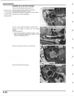
Page 88: ...ngine and wait 3 minutes Support the motorcycle upright on a level surface Remove the oil filler cap dipstick Place an oit pan under the engine to catch the oil 1 3 EEl Remove the engine oil drain bolt and sealing washer Drain the engine oil 10 Operate the kickstarter pedal five times or more while pushing the engine stop switch so the engine oil completely drains Remove the bolts oil filter cover...

Page 89: ...SIDE mark facing out I NOTICE I Installing the 0 1 filter reverse side will result in severe engine damage Apply engine oil to a new O ring and install it to the oil filter cover Install the oil filter cover and tighten the bolts securely Fill the engine with the recommended oil OIL CAPACITY 0 67 liter 0 71 US qt 0 59 Imp qtJ at draining 0 70 liter 0 74 US qt 0 62 Imp qt at oil filter change Insta...

Page 90: ... let it idle for 3 minutes 2 Stop the engine and wait 3 minutes 3 Support the motorcycle upright on a level sur face 4 Remove the oil filler cap oil check bolt and seat ing washer from the right crankcase cover A small amount of oil should flow out of the check bolt hole 5 If no oil flows out of the check bolt hole add rec ommended transmission oil slowly through the oil filler hole until oil star...

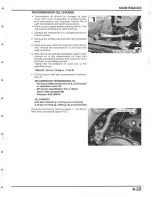
Page 91: ...washer 4 After the oil has drained completely apply trans mission oil to the transmission oil drain bolt threads and seating surface then install the drain bolt with a new sealing washer Tighten the transmission oil drain bolt to the specified torque TORQUE 16 N m 1 6 kgf m 12Ibf ft 5 Fill the engine with the recommended transmis sion oil RECOMMENDED TRANSMISSION OIL Pro Honda GN4 4 stroke oil U S...

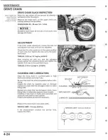
Page 92: ...t the adjusters snugly against the adjusting blocks and tighten the adjuster lock nuts to the specified torque TOROUE 27 N m 2 8 kgf m 20 Ibl ft CLEANING AND LUBRICATION Clean the drive chain in non flammable or high flash point solvent and wipe it dry SOFT BRUSH SOLVENT Be sure the chain has dried completely before lubri cating Inspect the chain for possible wear or damage replace any chain that ...

Page 93: ...rive chain with a staked master link loosen the drive chain page 4 24 Assemble the speciel tool as shown TOOL Drive chain tool set 07HMH MR10103 or 07HMH MR1010C U S A only l ocate the crimped pin ends of the master link from the outside of the chain and remove the link with the drive chain tool set TOOL Drive chain tool set Remove the drive chain 07HMH MR10103 or 07HMH MR101OC U S A only 80 90 GE...

Page 94: ...sert rhe master Assemble the new master link O rings and plate link from the inside of the drive cham and Ins all the pleTe with rhe ICIemlflCBllOfI mart fBCing The OUTSide Assemble and set the drive chain tool set TOOL Drive chain tool set 07HMH MR10103 or 07HMH MR101OC U S A only DRIVE CHAIN TOOL SET Make sure that the master link pins are installed properly MASTER LINK PINS Measure the master l...

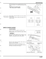
Page 95: ...nd plate DRIVE CHAIN SLIDER CHAIN SUDER Inspect the drive chain slider for excessive wear SERVICE LIMIT 5 0 mm 0 20 in from upper surface I NOTICE I If the chain slider becomes worn through to the 5wingarm the chain will wear against the swingarm damaging the chain and swingBrm GOOD NO GOOD v CRACKED CHAIN SLIDER Check the chain guide and chain guide slider for alignment wear or damage 05 07 shown...

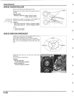
Page 96: ... 12 N m 11 2 kgf m 9 rbl tt Dri l8 chain roller nut 12 N m 1 2 kgf m 9 rbf tt NOTE Upper roller Green Lower roller Black DRIVE DRIVEN SPROCKET MARK Inspect the drive and driven sprocket teeth for wear 4 28 or damage replace them if necessary Never use a new drive chain on worn sprockets Both chain and sprockets must be in good condi tion or the new replacement chain will wear rap idly Check the bo...

Page 97: ...tire system for leaks page 4 29 FRONT BRAKE Turn th e handlebar so that the reservoir is level and check the front brake fluid level If the level is near the lower level line check the brake pad wear page 4 30 REAR BRAKE Support the motorcycle in an upright position on a r level surface If the level is near the lower level line check the brake pad wear page 4 30 FLUID FILLING Inspect the brake hos...

Page 98: ...ION INSPECTION The brake lever position can be adjusted by 1 005en ing the lock nut and turning the adjuster Turning the adjuster clockwise moves the brake lever farther away from the grip turning the adjuster counterclockwise moves the brake lever closer to the grip Apply grease to the After adjustment hold the adjuster and tighten the contact faces of the lock nut to the specified torque adjuste...

Page 99: ... Measure the clutch lever freeplay at the lever end FREEPLAY 10 20 mm 3 8 13 16 in Minor adjustments can be made with the cable end adjuster Turning the cable end adjuster in direction A will increase freeplay and turning it in direction B will decrease freeplay If the adjuster is threaded out near its limit and the correct freeplay cannot be reached turn the adjuster in direction A until it seats...

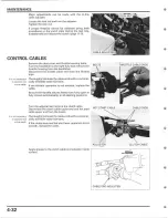
Page 100: ...he handlebar Disconnect the throttle cable end from the throttle pipe Thoroughly lubricate the cable ends with a commer cially available cable lubricant If the throttle operation is not smooth replace the cable Be sure the throttle returns freely from fully open to fu lly closed automatically in all steering positions Turn the adjuster and remove the clutch cable Disconnect the clutch cable upper ...

Page 101: ...t 21 N m 2 1 kgf m 15lbf ftJ Muffler joint band bolt 21 N m 12 1 kgf m 15 Ibf ft SPARK ARRESTER REMOVAL Remove the bolts spark arrester assembly and gas ket INSPECTION CLEANING Check the mesh screen is in good condition Use a soft brush to remove carbon deposits from the spark arrester screen Be careful to avoid dam aging the spark arrester screen The spark arrester must be free of breaks and hole...

Page 102: ...y Check the pivot bolt and nut on the sidestand Tighten the pivot bolt to the specified torque Loosen the pivot bolt counterclockwise 45 90 and tighten the pivot nut to the specified torque while holding the pivot bolt TORQUE Sidestand pillot bolt 10 N m 1 0 kgf m 7 IbHt 45 to 90 Sidestand pillot nut 39 N m 4 0 kgf m 29 Ibf it SUSPENSION 4 34 FRONT SUSPENSION INSPECTION Check the action of the for...

Page 103: ...ON INSPECTION Check the action of the shock absorber by com pressing it several times Lift the sub frame page 6 11 Check the entire shock absorber assembly for signs of leaks damage or loose fasteners Replace damaged components which cannot be repaired Tighten all nuts and bolts For shock absorber service page 15 14 l ower the sub frame page 6 25 SWINGARM SHOCK LINKAGE Raise the rear wheel off the...

Page 104: ... that atl safety clips hose clamps and cable stays are in place and properly secured WHEELS TIRES 4 36 Raise the front wheel off the ground by placing a workstand or equivalent under the engine Hold the fork leg and move the front wheel side ways with force to see jf the wheel bearings are worn Raise the rear wheel off the ground by placing a workstand or equivalent under the engine Hold the swing...

Page 105: ...se spokes and rim locks to the speci fied torque TOOLS FRONT Spoke wrench 6 1 mm REAR Spoke wrench 6 6 mm TORQUE Front spoke 07JMA MR60100 or 0770 0020300 6 1 mml 070MA KZ30100 3 68 N m 0 4 kgf m 2 7 Ibf ft Rear spoke 3 7 N m 0 4 kgf m 2 7Ibf ft Front rear rim Lock 12 N m 11 2 kgf m 9Ibf ft STEERING HEAD BEARINGS Raise the front wheel off the ground by placing a workstand or equivalent under the e...

Page 106: ...abbing the fork legs and attempting to move the front fork for ward to backward If the handlebar moves unevenly binds or has ver tical movement inspect the steering head bearings page 14 48 If excessive play has detected check the steering stem for cracks 1 ...

Page 107: ...5 LUBRICATION SYSTEM LUBRICATION SYSTEM DIAGRAM 5 2 PRESSURE RELIEF VALVE 5 5 SERVICE INFORMATION 5 3 OIL JET 5 6 TROUBLESHOOTING 5 3 OIL PUMP 5 7 OIL STRAINER 5 4 5 1 ...

Page 108: ...LUBRICATION SYSTEM LUBRICATION SYSTEM DIAGRAM 05 07 shown OIL JET OIL PUMP _ _ PRESSURE REUEF VALVE Oil PUMP GEAR CRANKSHAFT 5 2 OIL STRAINER SCREEN PISTON MAINSHAFT ...

Page 109: ...vice limits replace the oil pump as an assembly After the oil pump has been installed check that there are no oil leaks and that oil pressure is correct SPECIFICATIONS pump TORQUE VALUE Canada or equivalent motor oil API service classification SG or Higher MA Canadal or equivalent motor i API service classification SG or Higher JASO T 903 standard MA SAE lOW 30 Oil jet mounting bolt 10 N m 1 0 kgf...

Page 110: ...cer page 13 8 Remove the snap ring and oil pump driven gear Remove the drive pin Remove the bolts guide plates oil strainer and grommet Remove the O ring from the oil strainer Check the oil strainer for damage or clogs Clean the oil strainer screen Check the oil pump driven gear for wear or damage Oil STRAINER Oil PUMP DRIVEN GEAR ...

Page 111: ...tall the drive pin into the oil pump shatto Install the oil pump driven gear aligning its cut outs with t he drive pin Install the snap ring securely Install the following Balancer page 13 8 Flywheel page 12 6 Left crankcase cover page 12 6 PRESSURE RELIEF VALVE REMOVAL INSPECTION Remove the left crankcase cover page 12 4 Remove the snap ring and pressure relief valve from the left crankcase cover...

Page 112: ... onto the pressure relief valve Install the pressure relief valve into the left crankcase cover Install the snap ring securely Install the left crankcase cover page 12 6 REMOVAL INSPECTION Separate the left and right crankcase halves page O 13 10 Remove the bolt and oil jet from the left crankcase Check the left crankcase oil passage for clogging Clean the oil passage Check the oil jet for damage ...

Page 113: ...ft and right crankcase halves page 13 10 Remove the oil pump inner outer rotors and shaft Remove the one way valv8 INSPECTION Check the one way valve for wear or damage Check the oil pump shaft for wear or damage Check the left crankcase cover oil seal for damage or deterioration Replace the oil seal if necessary After installing B Check that the washer and snap ring are installed in snap ring alw...

Page 114: ...he body clearance STANDARD 0 15 0 21 mm 0 006 0 008 in Measure the side clearance using a straight edge and feeler gauge STANDARD 0 05 0 13 mm 0 002 0 005 In ASSEMBLY Apply oil to the oil pump inner outer rotors sliding surlaces Install the oil pump inner outer rotors and shaft Install the one way valve onto the left crankcase as shown Assemble the left and right crankcase halves page 13 25 Instal...

Page 115: ...CARBURETOR ASSEMBLy 6 18 TROUBLESHOOTING 6 5 CARBURETOR INSTALLATION 6 24 CARBURETOR ADJUSTMENT 6 6 THROTTLE POSITION SENSOR REPLACEMENT 6 26 AIR CLEANER HOUSING 6 7 PILOT SCREW ADJUSTMENT 6 27 CARBURETOR REMOVAL 6 11 SECONDARY AIR SUPPLY SYSTEM 05 and 06 California type After 061 6 29 6 1 ...

Page 116: ...FUEL SYSTEM COMPONENT LOCATION OS 07 shown 3 4 N m 10 3 2 5Ibf ft r After 07 i i 49 15 0 kgf m 36 Ibf ft 6 2 ...

Page 117: ...lug remove the drain plug and drain the carburetor When disassembling the fuel system parts note the locations of the O rings Replace them with new ones on reassem biV After removing the carburetor wrap the intake port of the engine with a shop towel or cover it with a piece of tape to prevent any foreign material from dropping into the engine Be sure to remove the cover when reinstalling the carb...

Page 118: ...5 06 After 06 05 06 After 06 13 N m 0 3 kgf m 10 Ibf tt 30 N m 3 1 kgf m 22 Ibf ft 49 N m 5 0 kgf m 3S IbHt 49 N m 5 0 kgf m 36 Ibf ft 44 N m 4 5 kgf m 32 Ibf ft 3 4 N m 0 3 kgf m 2 5 Ibf ft 1 8 N m 0 2 kgf m 1 3 Ibf ft 1 5 N m 0 2 kgf m 1 1 Ibf ft 0 9 N m 0 1 kgf m 0 7 lbf ft 1 5 N m 0 2 kgf m 1 1 IbUtl 1 5 N m 0 2 kgf m 1 1 Ibf ft 0 3 N m 0 03 kgf m 0 2 Ibf ft 2 1 N m 0 2 kgf m 1 5 Ibf ft 2 1 N ...

Page 119: ... during acceleration Ignition system faulty page 18 5 Lean mixture Accelerator pump faulty Rich mixture Choke valve in the ON posit ion Float valve faulty Float level too high Air jets clogged Air cleaner element contaminated Flooded carburetor Engine stalls hard to start rough idling Fuel line restricted Ignition system malfunction page 18 5 Low cylinder compression Fuel mixture too lean rich Fue...

Page 120: ... When the engine is warm enough to run without the choke push the choke knob in to its off posi tion 2 Turn the throttle stop screw to obtain the smoothest idle To decrease idle speed turn the throttle slop screw counterclockwise To increase idle speed turn the throttle stop screw clockwise 3 Adjust the pilot screw to obtain the best off idle performance If the engine runs rich exiting a corner tu...

Page 121: ...n the air cleaner connecting boot band screw Unhook the band and air cleaner case cover from the fuel tank Remove the sub frame lower mounting bolts and loosen the upper mounting bolts Lift the sub frame as shown Tighten the sub frame upper mounting bolts to the specified torque TORQUE 05 07 30 N m 3 1 kgf m 22 lbf ft After 07 49 N m 15 0 kgf m 36 Ibf ft Except 05 and 06 Disconnect the crankcase b...

Page 122: ...move the screws and mud guard Remove the botts collars and air cleaner housing Check the carburetor connecting boot is sealed properly at the air cleaner housing Check the air cleaner housing for damage Remove the carburetor connecting boot from the air cleaner housing and seal thoroughly if any sign of inadequate sealing is detected ...

Page 123: ... collars and bolts and hoses properly 05 07 page 25 Aha 07 page 32 Be C8reful not Tighten the rear fender mounting boilS to the speci fied torque TORQUE 13 N m 1 3 kgf m 10 Ibf ft to damage the WIres Jnd hoses Install the mud guard and tighten the screws securely_ Install the collar and bolt Tighten the bolt securely AIR CLEANI R HOUSING MUD GUARD AIR CLEANER ElEMENT ELEMENT HOLDER AIR CLE NE 6 9 ...

Page 124: ...frame mounting bolts to the speci fied torque TORQUE 05 07 Upper 30 N m 3 1 kgf m 22 Ibf ft lower 49 N m 5 0 kgf m 36 Ibf ft TORQUE After 07 Upper lower 49 N m 5 0 kgf m 36 Ibf ft Tighten the air cleaner connecting boot band screw securely Hook the air cleaner case cover and band securely to the fuel tank Install the following Banery page 17 6 Regulator rectifier page 17 8 Muffler 05 07 page 3 9 A...

Page 125: ...ing bolts and loosen the upper mounting bolts Do not lift Lift the sub frame as shown past 90 Be careful nor to dllmage the wires and CtJbles Tighten the sub frame upper mounting bolts to the specified torque TOROUE OS 07 30 N m 13 1 kgf m 22lbf ft After 07 49 N m 5 0 kgf m 36 Ibf ft FUEL SYSTEM SO UPPER MOUNTING BOLT Remove the shock absorber upper mounting nut Igiiii and bolt Pull back the shock...

Page 126: ...i hot start valve from the carburetor Disconnect the hot start cable end from the hot start valve and remove the valve spring Check the hot start valve for nicks grooves or other damage Check the hot start valve seat for wear Remove the bolt and throttle drum cover l oosen the lock nut throttle bolt adjuster and dis connect the throttle cables from the throttle drum Remove the carburetor to the re...

Page 127: ... hose Release the throttle position sensor wire from the clamp Remove the bolts clamp top cover and O ring 05 06 Remove the needle holder and jet needle After 06 Remove the jet needle holder assembly 05 06 Check the jet needle for wear nicks or other dam age FUEL SYSTEM FUEL HOSE TOP COVER JET NEEDLE 6 13 ...

Page 128: ...haft torx screw Lift up the throttle shaft arm and remove the throttle valve assembly Remove the throttle valve plate and roller from the throttle valva Check the throttle valva throttle valve seal roller and throttle valve plate for scratches wear or dam age Replace them if necessary CHOKE KNOB THROTTLE SENSOR Loosen the lock nut and remove the choke knob After 06 NEEDLE HOLDER CHOKE KNOB JET NEE...

Page 129: ... The throttle position sensor is factory pre set and no adjustment is necessary unless the throttle position sensor is replaced For sensor inspection page 1S 9 and replace ment page 6 26 ACCELERATOR PUMP FLOAT JETS Remove the screws and accelerator pump cover NOTE The accelerator pump cover is under spring pres sure Do not lose the screws and O ring Remove the spring diaphragm D ring and O ring 05...

Page 130: ...ush rod link lever adjusting lever screw is fac ory pre set Adjustment and disassembly are nor necessary 6 16 Check the diaphragm for deterioration or pin hole Check the spring for damage or fatigue Check the push rod for wear bends or damage Remove the float pin float and float valve Check the float for damage or fuel in the float Replace the float jf necessary FLOAT CH AMISER STAY O RING SPRING ...

Page 131: ... for wear or damage Clean or replace them jf necessary Remove the following Main jet Needle jet Baffle plate Starter jet Slow jet Before removing the pilot screw turn it in counting the number of turns until it seats tightly so you can return the pilot screw to its original position when reassembling Remove the pilot screw spring washer and O ring 05 07 Remove the slow air jet Remove the acc pump ...

Page 132: ...open all carburetor body openings with com pressed air SLOW JET PilOT SCREW SLOWAIRJET 05 071 NEECLE JET MAIN JET STARTER JET CARBURETOR ASSEMBLY TOP COliER NEEDLE HOLDER NttOLtClIP NEEDLE HOLDER PUSH ROD STARTER JET um A JET 05 07 THROTTLE VALVE Ace PUMP BYPASS BAFFLE PLATE NEEDLE JET SLOW THROTTLE pn ITlnN SENSOR CHOKE KNOB FLOAT VALVE FLOAT O RING FLOAT CHAMBER THROTTLE STOPSCAEW DIAPHRAGM O RI...

Page 133: ...r sensor inspection page 18 9 and replace ment page 6 26 Damage to the pilot Install the O ring washer spring and pilot screw screw seat Will Perform pilot screw adjustment if a new pilot screw occur if the pilot screw is tightened against rhe sear is installed page 6 27 Install the pilot screw and return it to its original position as noted during removal Install the slow jet starter jet baffle p...

Page 134: ...loat is level with the float level gauge TOOL Carburetor float level gauge 07401 0010000 FLOAT LEVEL 8 0 mrn 10 31 in If the float level is oul of specification adjust it by bending the lip Install the push rod while holding the push rod link lever Install the acc pump bypass into the float chamber and tighten it to the specified torque TORQUE 0 3 N m 0 03 kgf m 0 2 Ibf ft Install a new O ring to ...

Page 135: ...Install a new D ring with it flat side facing forward r ru NG the accelerator pump cover Install the diaphragm spring new Q rings and ItiijiIII accelerator pump cover Install and tighten the screws to the specified torque TORQUE 2 1 N m 0 2 kgf m l 5Ibf ft Install the choke knob and tighten the lock nut to the specified torque TORQUE 2 1 N m 0 2 kgf m 1 5Ibf ftl 05 07 shown CHOKE FUEL SYSTEM 6 21 ...

Page 136: ...rm and throttle shaft 05 06 Apply locking agent to the screw threads Install and tighten the throttle shaft screw to the specified torque TORQUE 2 1 N m 0 2 kg m 1 5 IbHt After 06 Apply locking agent to the torx screw threads Install and tighten the throttle shaft torx screw to the specified torque TORQUE 2 1 N m 0 2 kgf m 1 5Ibf ft 05 06 Install the jet needle clip to the jet needle STANDARD CLIP...

Page 137: ...r assemblv to the speci fied torque TORQUE 2 1 N m 0 2 kgf m 1 5 Ibf ft Install a new D ring and top cover Install the clamp and bolts Tighten the bolts to the specified torque TORQUE 2 1 N m 0 2 kgf m 1 5 rbf ttl Clamp the throttle position sensor wire as shown ROllla the hoses Connect the overflow hose air vent hoses and fuel property 05 07 hose pag9 1 25 After 07 page 1 32 FUEL SYSTEM 05 06 sho...

Page 138: ...rum cover and bolt Tighten the bolt to the specified torque TORQUE 3 4 N m 0 3 kgf m 2 5 Ibf ft Install the valve spring over the hot start cable and connect the cable end to the hot start valve Install the hot start valve to the carburetor body and tighten the lock nut to the specified torque TORQUE 2 1 N m 0 2 kgf m 1 5 Ibf ft Align the lug on the carburetor with the groove in the carburetor ins...

Page 139: ...gf m 22 Ibf ft lower 49 N m 5 0 kgf m 36 Ibf ft TORQUE After 07 Upper lower 49 N m 5 0 kgf m 36 IbUt Tighten the air cleaner connecting boot band screw P securely Install the following Muffler OS 07 page 3 9 After 07 page 3 11 Fuel tank page 3 8 Seat page 3 3 After installation check the following Secondary air leak around the insulator and con necting boot Fuel leaks around the fu el hose and car...

Page 140: ...ly install the bolt Measure the resistance between the Blue and Black wire terminals of the sensor side connector STANDARD 4 6 kO 20cC 68 F Calculate the throttle position sensor resistance at idle speed using the equation below Ax O 13 0 15j B A Blue and Black wire terminals resistance B Throttle position sensor resistance at idle speed Ex If the Blue and Black wire terminals resistance is 5 kfl ...

Page 141: ...ll accurately indicate a 50 rpm change BEST IDLE 05 06 49 States and Canada type only DamaQ8 to the pilot 1 screw seat will occur if the pilor screw is tightened against the seat Turn the pilot screw clockwise until it seats lightly then back it out the specified number of turns TOOL Pilot screw w rench 07908 4730002 STANDARD OPENING 1 114 tums out 2 Warm up the engine to operating temperature Rid...

Page 142: ...rns out After 01 1 118 turns out 2 Warm the engine up to operating temperaturB Stop and go riding for 10 minutes is sufficient 3 Stop the engine and connect a tachometer according to its manufacturer s instruction 4 Disconnect the PAIR control valve vacuum hose and plug it to keep air from entering then con nect the vacuum pump to the PAIR control valve vacuum hose joint 5 Apply the specified vacu...

Page 143: ...he plug from the vacuum hose then disconnect the vacuum pump and connect the vacuum hose to the PAIR control valve 12 Readjust the idle speed with the throttle stop screw IDLE SPEED 1 700 100 rpm Disconnect the tachometer SECONDARY AIR SUPPLY SYSTEM 05 and 06 California type After 06 SYSTEM INSPECTION Warm up the engine to normal operating tempera ture Check that the secondary air intake port is c...

Page 144: ...t the PAIR air suction hose stops drawing air and that the vacuum does not bleed SPECIAEO VACUUM 56 kPa 420 mmHg If the air is drawn in or if the specified vacuum is not maintained install a new PAIR control valve PAIR CONTROL VALVE REMOVALI INSTALLATION Remove the right radiator shroud page 3 4 SIJ EE Disconnect the vacuum air supply and PAIR air sue tion hoses Remove the bolts nuts stay and PAIR...

Page 145: ...the reverse order of removal AIR SUPPLY PIPE REMOVAL INSTALLATION Remove the radiator shroud page 3 4 Remove the bolt Disconnect the air supply hose Remove the air supply pipe and O ring Check the air supply pipe for damage or deforma tion Install a new O ring onto the air supply pipe Installation is in the reverse order of removal AIR SUPPLY PIPE FUEL SYSTEM VALVE STOPPER RUI B HSEAT 6 31 ...

Page 146: ...MEMO ...

Page 147: ...7 COOLING SYSTEM SYSTEM FLOW PATTERN 7 2 COOLANT REPLACEMENT 7 6 SERVICE INFORMATION 7 3 RADIATOR 7 8 TROUBLESHOOTING 7 4 RADIATOR RESERVE TANK 7 9 SYSTEM TESTING 7 5 WATER PUMP 7 9 r 7 1 ...

Page 148: ...COOLING SYSTEM SYSTEM FLOW PATTERN 7 2 o a0 WATER PUMP RESI R ETANK ...

Page 149: ... coolant at the reserve tank Do not remove the radiator cap except to refill or drain the system All cooling system services can be done with the engine in the frame Avoid spilling coolant on painted surfaces After serviCing the system check for leaks with a cooling system tester SPECIFICATIONS or an I antifreeze containing silicate free TORQUE VALUE Water pump impeller TOOLS Mechanical seal drive...

Page 150: ...assage blocked in radiator hoses or water jacket Radiator air passage clogged with dirt Air in system Faulty water pump Coolant leak Faulty water pump oil seal and mechanical seal Deteriorated water pump oil seal and mechanical seal Damaged or deteriorated D ring l oose hose connection or clamp Damaged or deteriorated hose Faulty radiator cap Damaged radiator Passage blocked in radiator siphon hos...

Page 151: ...e sure the engine is cool remove the radiator cap Test the coolant specific gravity using a hydrome ter STANDARD COOLANT CONCENTRATION 1 1 Look for contamination and replace the coolant if Io ol necessary COOLANT GRAVITY CHART COOLING SYSTEM 7 5 ...

Page 152: ...e pressure install the radiator cap securely COOLANT REPLACEMENT PREPARATION If any coolant gets in your eyes rinse them with 7 6 water and consult a doctor immediately If any coolant in swallowed induce vomiting gargle and consult a physician immediately If any coolant gets on your skin or clothes rinse thoroughly with plenty of water The effectiveness of coolant decreases with the accumulation o...

Page 153: ...rve tank cap and reserve tank Drain the reserve tank coolant Empty the coolant and rinse the inside of the reserve tank with water Reinstall the reserve tank and connect the radiator siphon hose Install the right and center engine guard page 3 5 Fill the system with the recommended coolant through the filler opening up to the filler neck CAPACITY 1 21 liter 1 28 US qt 1 06 Imp qt at change Lean th...

Page 154: ... proper level if necessary Reinstall the radiator cap 4 Check the level of coolant in the reserve tank and fill to the UPPER level line if it is low RADIATOR REMOVAL INSTALLATION Drain the coolant page 7 7 Remove the fuel tank page 3 8 Remove the radiator grills Note the direction Disconnect the following of the water hose clamp 8e careful not to damage the radiator core 7 8 Siphon hose Connecting...

Page 155: ...ank cap and reserve tank Disconnect the radiator siphon and reserve tank overflow hoses from radiator reserve tank Drain the reserve tank coolant Route tile hoses Installation is in the reverse order of removal Pf0p8r y 05 07 page 1 25 Aher 07 page 1 J2 WATER PUMP MECHANICAL OIL SEAL INSPECTION Check for signs of seal leakage If water leaks through the bleed hole replace the mechanical seal page 7...

Page 156: ...e coolant page 1 7 Remove the bolts water hose joint and O ring Remove the drain bolt and sealing washer Remove the bolts and water pump cover Remove the O ring and dowel pin Loosen the impeller Remove the right crankcase cover page 11 5 ...

Page 157: ...ietly Also check that the bearing outer race fits tightly in the right crankcase cover Replace the water pump shaft bearing if the inner race does not turn smoothly quietly or if the outer race fits loosely in the right crankcase cover Check the mechanical seal for damage or deteriora tion Replace the mechanical seal if necessary page 7 12 COOLING SYSTEM WATER PUMP SHAFT RIGHT CRIINKCA 5E COVER WA...

Page 158: ...Remover handle Remover weight 07936 660101 not available in U S A 0774 0010201 07936 1660 0 not available in U S A 07936 660120 not available in U S A 07936 166010A 07936 3710100 07741 0010201 or 07936 371020A Check the oil seal for damage or deterioration replace it if necessary page 7 12 Remove the mechanical and oil seals from the right crankcase cover Apply grease to the oil seal lips Install ...

Page 159: ...r Mechanical seal driver 07945 4150400 Apply grease to new mechanical seal lips Drive in a new bearing into the right crankcase cover using the special tools as shown TOOLS Driver Attachment 28 x 30 mm Pilot 12mm Apply oil to new oil seal lips INSTALLATION WATER PUMP SHAFT BEARING 07749 0010000 07946 1870100 07746 0040200 L QILSEAL o IMPELLER COOLING SYSTEM jjffi MECHANICAL SEAL WATER PUMP COVER 1...

Page 160: ...over page 11 6 Tighten the impeller to the specified torque TORQUE 12 N m 11 2 kgf m 9Ibf ft Install a new O ring onto the water pump cover Install the dowel pin WASHER IMPELLER o WATER PUMP SHAFT RIGHT CRANKCASE COVER Install the water pump cover and tighten the bolts securely Install the drain bolt and a new sealing washer Tighten the drain bolt securely 7 14 ...

Page 161: ... ring into the water hose joint groove Install the water hose joint onto the water pump cover and tighten the bolts securely Fill the system with the recommended coolant and bleed the air page 7 7l COOLING SYSTEM 7 15 ...

Page 162: ...MEMO ...

Page 163: ...8 ENGINE REMOVAL INSTALLATION COMPONENT LOCATION 8 2 ENGINE REMOVAL 8 5 SERVICE INFORMATION 8 3 ENGINE INSTALLATION 8 8 DRIVE SPROCKET 8 4 l 8 1 ...

Page 164: ...NSTALLATION COMPONENT LOCATION 05 01 shown 26 N m 2 7 kgf m 191bf hl 9 0 kgf m 65 Ibf ftj After 07 54 N m 5 5 kgf m 40 Ibf ft 54 N m 1 5 5 kgf m 38 N m 3 9 kgf m 28 Ibf ft 31 N m 3 2 23Ibf ft 21 2 1 kgf m 15Ibf ft 8 2 ...

Page 165: ...Secondary air supply system OS and 06 California type After 06 page 6 31 Flywheel page 12 5 Water pump page 7 9 Balancer page 13 8 Starter clutch page 11 19 Starter motor page 19 6 SPECIFICATIONS equ val nt motor service classification SG or Higher T903 standard MA TORQUE VALUES Engine hanger plate bolt Engine mounting nut Drive sprocket bolt Kickstarter pedal bolt Swingarm pivot nut Exhaust pipe ...

Page 166: ...nut loosen the drive chain adjuster lock nuts and turn the adjusters clockwise fully Remove the botts sprocket cover and spacer Shift the transmission other than neutral position Remove the bolt collar washer and drive sprocket INSTALLATION Install the drive chain to the drive sprocket Install the drive sprocket onto the countershaft with the OUT mark facing out ...

Page 167: ...3 3 left right center engine guards page 3 5 Fuel tank page 3 8 Spark plug cap page 4 12 Ignition coil page 18 8 Exhaust system page 3 13 Carburetor page 6 1 1 Drive sprocket page 8 4 Kickstarter pedal page 11 5 Gearshift pedal page 1 24 Brake pedal page 16 24 Radiator reserve tank page 7 9 05 and 06 Remove the PAIR control valve page 6 30 California type Disconnect the breather hoses After 06 Rem...

Page 168: ...disconnect the radiator hoses Remove the bolt water hose joint and O ring from the cylinder head Remove the nut bolts fuel hose guide clutch cable guide and engine hanger plates loosen the swingarm pivot nut Loosen the engine front and lower mounting nuts Remove the swingarm pivot nut washer and bolt Remove the engine front and lower mounting nuts washers and bolts Remove the engine A workstand or...

Page 169: ...tion coil stays NOTE After 07 Be careful not to damage the cylinder head cover with the ignition coil stay upper only 2 Move the fBar end of the engine over the swingarm pivot of the frame 1 Position the water hose joint inside of the front engine hanger Remove the engine from the right side of the frame using the following procedures 05 07 show n 1 Lift the bottom of the engine and pass the water...

Page 170: ...ngine mounting bolts washers and nuts Route the wires and cables properly 05 07 page 1 25 After 07 page 1 32 Do not tighten the swingarm pivot nut and engine mounting nuts yet Install the engine hanger plates fuel hose guide clutch cable guide upper engine mounting bolt washer nut and engine hanger plate bolts Tighten the engine mounting nuts engine hanger plate bolts and swingarm pivot nut to the...

Page 171: ...6 24 Gearshift pedal page 1 27 Kickstarter pedal page 11 7 Drive sprocket page 8 4 Carburetor page 6 24 Exhaust system page 3 14 Spark plug cap page 4 12 Fuel tank page 3 8 Left right canter engine guards page 3 5 Seat page 3 3 05 and 06 Install the PAIR control valve page 6 301 callfom type After 06 Fill the system with the recommended coolant and bleed the air page 7 71 Fill the engine with the ...

Page 172: ...MEMO ...

Page 173: ...INDER COMPRESSION TEST 9 7 CYLINDER HEAD ASSEMBLy 9 33 CYLINDER HEAD COVER REMOVAL 9 7 CYLINDER HEAD INSTALLATION 9 36 CAMSHAFT REMOVAL 1 05 07 9 8 CAMSHAFT INSTALLATION CAMSHAFT REMOVAL IAfter 07 9 16 OS 07 9 37 CYLINDER HEAD REMOVAL 9 24 CAMSHAFT INSTALLATION IAfter 07 9 39 CAM CHAIN TENSIONER CAM CHAIN GUiDE 9 25 CYLINDER HEAD COVER INSTALLATION 9 42 CYLINDER HEAD DiSASSEMBLy 9 27 9 1 ...

Page 174: ...CYLINDER HEADIVALVES COMPONENT LOCATION 05 07 shown 10 N m 11 0 gf m 7 Ibf ftJ After 07 _ 66 N m 6 7 kgf m 49 Jbf ft 20 N m 2 0 kgf m 15 Ibf ft 9 2 ...

Page 175: ...IFICATIONS valve guide I TORQUE VALUES Cylinder head cover bolt Camshaft holder mounting bolt Decompressor cam mounting bolt 05 07 Cam sprocket bolt Decompressor lifter arm mounting nut OS 07 Cylinder head nut Cam chain tensioner bolt Crankshaft hole cap Engine mounting nut Engine hanger plate bolt Spark plug upper EX 17 9 18 1 0 70 0 71 10 N m 1 0 kgf m 7 Ibf ft 14 N m 1 4 kgf m 10 Ibf ft 24 N m ...

Page 176: ...ve guide driver 07743 0020000 not available in U S A Valve seat cutter 35 mm 45 IN 07780 0010400 or equivalent commercially avail able in U S A Flat cutter 36 mm 32 IN 07780 0013500 or equivalent commercially avail able in U S A Valve guide remover 5 0 mm 07942 MASOOOO Valve guide reamer 5 5 mm 07984 2000001 or 07984 2000000 U S A only Valve seat cutter 33 mm 45 EX 07780 0010800 or equivalent comm...

Page 177: ...r stopper 070MG 0010100 or 07AMG 001A100 U S A only Cutter holder 5 0 rnm 07781 0010400 or equivalent commercially avail able in U S A Pilot 20 mm 07746 0040500 Cam sprocket holder 05 07 07AMB MEBA100 U S A only CYLINDER HEADIVALVES Driver 07749 0010000 Cutter holder 5 5 mm 0778 0010101 or equivalent commercially avail able in U S A 9 5 ...

Page 178: ...k valve spring Uneven valve seating Valve stuck open Cylinder head leaking or damaged cylinder head gasket Warped or cracked cylinder head loose spark plug Faulty cylinder piston or piston rings Faulty decompressor system Compression too high Excessive carbon build up in cylinder head or top of piston Excessive smoke Worn valve stem or valve guide Damaged stem seal Cylinder piston or piston rings ...

Page 179: ...within 4 7 seconds when using electric starter COMPRESSION 402 kPa 4 1 kg cm2 58 psi at 360 rpm low compression can be caused by Improper valve adjustment Valve leakage Blown cylinder head gasket Worn piston ring or cylinder Faulty decompressor system High compression can be caused by Carbon deposits in combustion chamber or on piston head Faulty decompressor system CYLINDER HEAD COVER REMOVAL Rem...

Page 180: ... Make sure the piston is at TOC Top Dead Center on the compression stroke This position can be obtained by confirming that there is slack in the rocker arms If there is no slack rotate the crankshaft clockwise one full turn and align the punch mark on the primary drive gear with t mark on the right crankcase cover again Check that the index tine on the cam sprocket aligns with the I mark on the ca...

Page 181: ...et holder 07AMB MEBA100 U S A only 8 5 m i 0 m Remove the special tool turn the crankshaft clock I E wise one turn and reinsert the spedal tool into the sprocket Remove the other cam sprocket bolt Then remove the another cam sprocket bolt using the same procedure as removal of the other cam sprocket bolt Remove the cam sprocket from the camshaft and suspend the cam chain with a piece of wire to pr...

Page 182: ...rs from the camshaft holder valve liflers so finly assemblv can be Installed III rhelr onglflai POSit MS 9 10 DISASSEMBLY Remove the circlip and nut Remove the decompressor lifter spring and decompressor arm Remove the stopper ring VALVE LIFTERS DE ONIPR SSOR ARM ...

Page 183: ... rocker arm Remove the bolt stopper plate and decompressor cam assembly Remove the snap ring and camshaft from the cam shaft holder I NOTICE I Make sure the intake lobes afe faCing up when removing the camshaft from rhe holder to prevent damaging the intake litrer bores INSPECTION Inspect the camshaft contact surface of the rocker arm for wear or damage Measure the rocker arm 1 0 SERVICE LIMIT 12 ...

Page 184: ...ightly on the camshaft Replace the camshaft assembly if the bearing does not turn smoothly quietly or if it fits loosely on the camshaft Check the cam lobe surfaces for scoring or evidence of insufficient lubricant Measure the height of each cam lobe SERVICE LIMITS IN 36 890 mrn 11 4524 In EX 35 063 mm 1 3804 in NOTE Check the rocker arm if the cam lobe and valve lift ers are worn or damage Check ...

Page 185: ...race does not turn smoothly quietly or if it fits loosely in the cam shaft holder Apply oil to a new bearing Install a new bearing into the hub using the special tools TOOLS Driver Attachment 37 40 mm Pilot 20 mm 07749 0010000 07746 0010200 07746 0040500 Check the valve lifter bore scoring scratches or damage Measure each valve lifter bore I D SERVICE LIMIT 26 04 mm 1 025 in Check the valve lifter...

Page 186: ...to the camshaft journal and lobes Install the camshaft in the camshaft holder as shown I NOTICE I Make sure the intake lobes are facing up when installing the camshaft to prevent damaging the intake lifter bores Make sure the snap Install the snap ring into the groove in the camshaft ring is firmly seared holder in the groove Align the dowel pin Install the decompressor cam assembly on the decompr...

Page 187: ...e and valve slipper surfaces Install the rocker arm and rocker arm shaft into the camshaft holder Install a new stopper ring into the groove in the camshaft holder Install the decompressor arm decompressor lifter and spring Align the decompressor arm and decompressor lifter as shown Align the spring end and camshaft holder tab 85 shown CYLINDER HEADIVALVES ASSEMBLY BOLT STOPPER PLATE 9 15 ...

Page 188: ...drive gear with the w 6 mark on the right crankcase cover Make sure the piston is at TOC Top Dead Center on the compression stroke This position can be obtained by confirming that there is slack in the rocker arm If there is no slack rotate the crankshaft clockwise one full turn and match up the punch mark on the primary drive gear with 6 mark on the right crank case cover again Check that the ind...

Page 189: ... bolt Turn the crankshaft clockwise one turn again and remove the remaining cam sprocket bolt Remove the cam sprocket from the camshaft and cam chain Suspend the cam chain with a piece of wire to prevent it from falling into the crankcase Make sure the piston is at TOC Top Dead Center on the compression stroke l oosen the camshaft holder mounting bolts in a crisscross panern in two or three steps ...

Page 190: ...so they assembly can be ins ailed In their OfIgmal posmons DISASSEMBLY Remove the decompressor shaft and decompressor plunger Remove the stopper ring VALVE Thread a 6 mrn bolt into the rocker arm shaft and pull out the rocker arm shaft from the camshaft holder Remove the rocker arm 9 18 SHAFT ROCKER ARM ...

Page 191: ...ft from the holder to prevent damaging the intake lifter bores INSPECTION ROCKER ARM Inspect the camshaft contact surface of the rocker arm for wear or damage Measure the rocker arm 1 0 SERVICE LIMIT 12 05 mm 0 474 in ROCKER ARM SHAFT Inspect the rocker arm shaft for wear or damage Measure the rocker arm shaft 0 0 SERVICE LIMIT 11 92 mm 0 469 in Calculate the rocker arm te shaft clearance SERVICE ...

Page 192: ...ch cam lobe SERVICE LIMITS IN 36 890 mm 1 4524 in EX 35 063 mm 1 3804 in NOTE Check the rocker arm if the cam lobe is worn or damage OECOMPRESSOR SHAFT PLUNGER Check the decompressor shaft for bend or damage Check the decompressor plunger for wear or dam age Replace them if necessary CAM SPROCKET DECOMPRESSOR WEIGHT SPRING Check the cam sprocket teeth for wear or damage Check the decompressor weig...

Page 193: ...re scoring scratches or damage Measure each valve lifter bore 1 0 SERVICE LIMIT 26 04 mm 1 025 in VALVE LIFTER Check the valve lifter for scoring scratches or dam age Measure each valve lifter 0 0 SERVICE LIMIT 25 97 mm 11 022 in CAMSHAFT HOLDER BEARING REPLACEMENT Drive out the bearing Install a new bearing into the camshaft holder using the special tools TOOLS Driver Attachme nt 37 x 40 mm Pilot...

Page 194: ...y molybdenum oil solution to the camshaft journal and lobes Install the camshaft to the camshaft holder I NOTICE I Make sure the intake cam lobes are facing up when installing the camshaft to prevent damaging the intake lifter bores Make sure the snap Install the snap ring into the groove of the camshaft rmg s firmly sealed holder in the groove 9 22 CAMSHAFT CAMSHAFT HOLDER ...

Page 195: ...ew stopper ring into the groove of the camshaft holder Apply molybdenum oil solution to the decompressor plunger sliding surface and decompressor shaft 20 9 mm 14 mm 0 0 areas Install the decompressor plunger and decompressor shaft into the camshaft by aligning the groove on the plunger and pin on the shaft as shown CYLINDER HEADIVALVES ROCKER SH PPI R RING 9 23 ...

Page 196: ... 30 california type Drain the coolant page 7 7 After 06 Be careful not to let Remove the shims the shims fall into The shims can be easily removed with tweezers the cylinder 9 24 or a magnet Mark all valve shims so they can be installed in their original position Remove the upper engine mounting nut bolt and ir 1 fuel hose clamp 010 Remove the bolts clutch cable guide and engine hanger plates Loos...

Page 197: ...t tern in two or three steps r Be careful not to let Remove the nuts washers and cylinder head the nuts and washers fall into the left crankcase Remove the gasket and dowel pins CAM CHAIN TENSIONER CAM CHAIN GUIDE REMOVAL Remove the following Cylinder head page 9 24 Left crankcase cover page 12 4 Flywheel page 12 5 Remove the cam chain guide 9 25 ...

Page 198: ...HAIN TENSIONER Apply locking agent to the cam chain tensioner bolt E threads Install the cam chain tensioner coilar washer and bolt Tighten the bolt to the specified torque TORQUE 12 N m 1 2 kgf m 9 Ibf ft Install the cam chain guide by aligning the tabs with the grooves in the cylinder and the guide end with the groove in the crankcase Install the following Flywheel page 12 6 Left crankcase cover...

Page 199: ...ove the valve spring cotters using the special J G tension do nor tools compress the valve spring more than TOOLS necessary to Valve spring compressor remove the corrers Valve spring compressor attachment Mark all pans during disassembly so they can be installed in their orlglns iocations Remove the following Spring retainer Val ve spring Valve Stem seal Spring seat 07757 0010000 07959 KM30101 COT...

Page 200: ...ICE LIMIT 0 05 mm 0 002 in VALVE SPRING Check the valve springs for fatigue or damage Measure the free length of the intake and exhaust valve springs SERVICE LIMITS IN 39 7 mm 1 56 in EX 41 9 mm 1 65 in Replace the springs if they are shorter than the ser vice limits VALVEIVALVE GUIDE Inspect each valve for out af round burns scratches or abnormal stem wear Check the valve movement in the guide Me...

Page 201: ...rd valve guides are dimensions would bring the clearance within toler rep aced page 9 ance If so replace the guides as necessary and 29 ream to fit If the stem to guide clearance exceeds the service limits with new guides also replace the valves and guides VALVE GUIDE REPLACEMENT Mark new valve guides at the proper depth see specification page 9 30 using a marker Chill the new valve guides in a fr...

Page 202: ...mer clockwise or lean the reamer In the guide while eaming TOOLS IN Valve guide reamer 5 5 mm EX Valve guide reamer 5 0 mm 07984 2000001 or 07984 2000000 U S A onlv 07984 MA60001 or 07984 MA6000D U S A onlv Clean the cylinder head thoroughly to remove any metal particles after reaming and reface the valve seats page 9 30 VALVE SEAT INSPECTION REFACING 9 30 Clean the intake and exhaust valves thoro...

Page 203: ... the valve VALVE SEAT REFACING FOllow the reracing Valve seat cutters grinders or equivalent valve seat manufaCT urer s refacing equipment are recommended to correct operating worn valve seals mstruCf OfIS If the contact area is too high on the valve the seat must be lowered using a 32 flat cutter If the contact area is too Iowan the valve the seat must be raised using a 60 interior cutter CYLINDE...

Page 204: ...m EX Cutter holder 5 5 mm IN Cutter holder 5 0 mm EX 07780 0013500 01780 0012900 07781 0010101 07781 0010400 or equivalent commercially available in U S A Use a 60 interior cutter remove 1 4 of the existing valve seat material TOOLS Interior cutter 37 5 mm IN Interior cutter 34 mm EX Cutter holder 5 5 mm IN Cutter holder 5 0 mm EX 07780 0014100 07780 0014700 07781 0010101 07781 0010400 or equivale...

Page 205: ...e face and lap the exhaust valve using light pressure After lapping wash any residual compound off the cylinder head and valve I NOTICE I Excessive lapping pressure may deform or dam age the seat Change the sngle of the lapping tool frequently to prevent uneven seat wear Do not allow any lapping compound to enter the guides CYLINDER HEAD ASSEMBLY VALVE COnERS SPRING RETAINER SPRING SPRING SEAT tI ...

Page 206: ... spring retainers and exhaust spring retainers The intake spring retainer has a flat surface and the exhaust spring retainer has a chamfered edge Gresse IlIecolters Install the valve coners using the special tools as to ease ins allation shown To preV6n1loss of TOOLS 16nsion do nor Valve spring compressor compress rhe valve Valve spring compressor spnngs more than attachment necessary NOTE 07751 0...

Page 207: ... the carburetor insulator with the tab of the cylinder head Tighten the carburetor insulator band screw so the distance between the band ends is follow 05 07 12 0 1 0 mm 0 47 0 04 in After 07 9 0 1 0 mm 0 35 0 04 in Install a new D ring to the water hose joint Install the water hose joint to the cylinder head Install and tighten the bolt securely CYLINDER HEADIVALVES 05 07 INSULATOR Align After 07...

Page 208: ...stall the washers and cylinder head nuts the nuts and Tighten the nuts to the specified torque in a criss washers fallimo cross pattern in two or three steps the left crankcase 9 36 TOROUE 66 N m 6 7 kgf m 49 Ibf ft Install the cylinder head mounting bolts Tighten the cylinder mounting bolt and cylinder I head mounting bolts securely Connect the radiator hose to the water hose joint Tighten the ho...

Page 209: ...ll the PAIR control valve page 6 30 Californis type After 06 Fill the cooling system with recommended coolant mixture page 7 7 CAMSHAFT INSTALLATION 05 07 Apply molybdenum oil solution to the outer suriace of each valve lifter Install the lBlve Install the valve lifters into the camshaft holder lifters in their originsllocation Make sure the dowel pins are installed into the cam shaft holder Apply...

Page 210: ...cam sprocket bolt threads Align the cam sprocket bolt holes with the cam sprocket and camshaft Temporarily install the one cam sprocket bolt Turn the crankshaft clockwise 3600 and insert the special tool into the sprocket over the gasket sur face TOOL Cam sprocket holder 07AMB MEBA100 U S A only Tighten the other sprocket bolt to the specified l torque TORQUE 20 N m 2 0 kgf m 15 lbf ft Remove the ...

Page 211: ... kgf m 18 Ibf ft Check the O ring is in good condition replace it if necessary Apply oil to the O ring Apply grease to the crankshaft hole cap threads Install the crankshaft hole cap and tighten it to the specified torque TORQUE 15 N m 11 5 kgf m 11 Ibf ft Install the cylinder head cover page 9 42 CAMSHAFT INSTALLATION After 07 Turn the crankshaft clockwise to align the punch mark on the primary d...

Page 212: ... crisscross pattern in two or three steps to the specified torque TORQUE 14 N m 1 4 kgf m 10 Ibf ft Install the cam chain onto the cam sprocket When installing the cam sprocket align the follow ing Decompressor weight hole with the setting pin of 7 f the decompressor shaft Bolt hole of the cam sprocket with the camshaft Index line on the cam sprocket with the D mark of the camshaft holder Clean an...

Page 213: ... the stopper tool from the cam chain tensioner lifter Install the cam chain tensioner lifter bolt with a new sealing washer Tighten the cam chain tensioner lifter bolt securely Check the O ring is in good condition replace it if necessary Apply oil to the O ring Apply grease to the crankshaft hole cap threads Install the crankshaft hole cap and tighten it to the specified torque TORQUE 15 N m 5 kg...

Page 214: ...le seal Inspect the cylinder head cover packing for damage or deterioration and replace it with a new one jf nec essary Install the cylinder head cover packing to the cylin der head cover Install the washers to the cylinder head cover with their UP mark facing up UP MARK Install the cylinder head cover and tighten the bolts L r ii iiifiiii i 1 to the specified torque TORQUE 10 N m 1 0 kgf m 7 Ibf ...

Page 215: ... Connect the spark plug cap and breather hose Install the fuel tank page 3 8 CYLINDER HEADIVALVES 9 43 ...

Page 216: ...MEMO ...

Page 217: ... u COMPONENT LOCATION 10 2 SERVICE INFORMATION 10 3 TROUBLESHOOTING 10 4 CYLINDER REMOVAL 10 5 10 CYLINDER PISTON PISTON REMOVAL 10 6 PISTON INSTALLATION 10 9 CYLINDER INSTALLATION 10 10 10 1 ...

Page 218: ...CYLINDER PISTON COMPONENT LOCATION 10 2 05 07 ...

Page 219: ...n removing the cylinder For example do not use a screwdriver to pry the cylinder Clean all disassembled parts with cleaning solvent before inspection use compressed air to dry the parts Under racing conditions the piston and piston rings should be replaced after 15 0 hours of operation Replace the pis ton pin after 30 0 hours of operation SPECIFICATIONS ring Top 0 065 0 100 0 0026 0 0039 0 115 0 0...

Page 220: ...Compression too low hard starting or poor performance at low speeds Leaking cylinder head gasket Worn stuck or broken piston rings Worn or damaged cylinder and piston Loose spark plug Compression too high over heating or knocking Excessive carbon build up in cylinder head or on top of piston Abnormal noise Worn cylinder and piston Worn piston pin or piston pin hole Worn connecting rod small end Wo...

Page 221: ...er head page 9 24l Remove the cam chain guide Remove the bolts cam chain tensioner lifter and gasket Remove the bolt and cylinder Prevent the cam Remove the dowel pins and gasket chain from f811ing Into the crankcase CYLINDER PISTON 10 5 ...

Page 222: ...p at a point just opposite the gap spreading the ends 00 faf 10 6 CYLINDER INSPECTION Inspect the cylinder bore for wear or damage Measure the cylinder tD in the X and Y axes at three levels Take the maximum reading to determine the cylin der wear SERVICE LIMIT 96 025 mm 3 7805 in Calculate the cylinder to piston clearance Take a maximum reading to determine the clear ance For piston 0 0 page 10 7...

Page 223: ...up Measure the piston ring to ring groove clearance with the ring pushed into the groove SERVICE LIMIT 0 115 mm 10 0045 in Inspect the piston ring grooves for wear or damage Measure the diameter of the piston at 5 0 mm 0 20 in from the bottom and 90 degrees to the piston pin hole SERVICE LIMIT 95 94 mm 3 777 in If the 0 0 is under the service limit or nearly 15 0 hours of running time have elapsed...

Page 224: ... in Insert each piston ring into the cylinder and mea sure the ring end gap SERVICE LIMITS Top 0 45 mrn 0 018 in Oil side rail 0 90 mm 0 035 in CONNECTING ROD INSPECTION Measure the connecting rod small end 1 0 SERVICE LIMIT 19 04 mm 0 750 in If the 1 0 is over the service limit replace the crank shaft page 13 14 Calculate the connecting rod to piston pin clear ance SERVICE LIMIT 0 06 mm 0 002 in ...

Page 225: ... opening to prevent dust or dirt from emen ng the engine Be careful not to drop the piston pin cl o into the crankcase Clean any gasket material from the cylinder mating or u surfaces of the crankcase Apply molybdenum solution oil to the connecting rod small end Place a shop towel around the piston skirt and in the crankcase to prevent the piston pin clips from falling into the crankcase Apply eng...

Page 226: ... with l l N fR damago during engine oil and install the cylinder while compress installarion in9 the piston rings 10 10 Install the cylinder mounting bolt After tightening the cylinder head mounting nut tighten the cylinder mounting bolt securely Install a new gasket cam chain tensioner lifter and bolts Tighten the bolts to the specified torque TORQUE 12 N m 1 2 kgf m 9 Ibf ft ...

Page 227: ...Install the cam chain guide by aligning ils tabs with the grooves in the cylinder and the guide end with the groove in the crankcase Install the cylinder head page 9 36 CYLINDER PISTON 10 11 ...

Page 228: ...MEMO ...

Page 229: ... 11 CLUTCH STARTER CLUTCH KICKSTARTER GEARSHIFT LINKAGE COMPONENT LOCATION 2 SERVICE INFORMATION 3 TROUBLESHOOTING 4 RIGHT CRANKCASE COVER 5 CLUTCH 7 KICKSTARTER 5 STARTER CLUTCH 9 GEARSHIFT LINKAGE 24 11 1 ...

Page 230: ...RTER GEARSHIFT LINKAGE COMPONENT LOCATION 22 N m 2 2 kgf m 1 Ibf ft 12N m 1 2kgf m 9lbfft 18 N m 1 8 kgf m 13 Ibf ftj 108 N m 11 0 kgf m 80 rbf ft 80 N m 8 2 kgf m 59Ibf ft 11 2 12 N m 1 2 kgf m 9 rbf ft 12 N m 1 2 kgf m 9 lbf ftj ...

Page 231: ...E VALUES Clutch center lock nut Clutch spring bolt Gearshift drum center pin Gearshift drum stopper arm bolt Kid starter pedal bolt Gearshift pedal pinch bolt Gearshift return spring pin Primary drive gear bolt Starter gear holder mounting bolt TOOLS Clutch center holder 07724 0050002 or equivalent commercially avail able in U S A I I 80 N m 8 2 kgf m 59 Ibf ft 12 N m 1 2 kgf m 9 Ibf ft 22 N m 2 2...

Page 232: ...d or bent shift fork page 13 13 Damaged shift drum center groove Faul ty ratchet pawl Worn gear engagement dogs or slot page 13 12 Gearshift pedal will not return Weak or broken gearshift spindle return spring Bent gearshift spindle Clutch slips when accelerating Incorrect clutch adjustment Worn clutch discs Weak clutch springs Transmission oil mixed with molybdenum or graphite additives Motorcycl...

Page 233: ... the bolt and kickstarter pedal Remove the bolts water hose joint and D ring Loosen the right crankcase cover bolts in a criss cross pattern in two or three steps Remove the bolts hose guide hose clamp and right crankcase cover Remove the water by pass pipe and D ring Remove the gasket and dowel pins Check th e kickstarter spindle oil seal for deteriora tion or damage Apply grease to the kickstart...

Page 234: ...nkcase Install the dowel pins and new gasket Install the right crankcase cover while engaging the water pump shaft securely with the balancer shaft tab Install the hose clamp hose guide and right crank case cover bolts nghten the right crankcase cover bolts in a criss cross pattern in two or three steps Install a new D ring onto the water hose joint ...

Page 235: ... page 3 5 Brake pedal page 16 241 Fill the system with the recommended coolant and bleed the air page 7 7 Fill the transmission with the recommended trans mission oil page 4 22 Start the engine and check for oil and coolant leaks CLUTCH REMOVAL Remove the brake pedal page 16 24 Remove the bolts clutch cover and O ring Remove the clutch spring bolts in a crisscross pat tern in two or three steps Re...

Page 236: ...lock washer away from the lock nut Remove the clutch center lock nut using the special i tool TOOL Clutch center holder 07724 0050002 or equivalent com mercially avail able in U S A Remove the thrust washer and lock washer Remove the clutch center Remove the right crankcase cover page 11 5 Remove the thrust washer and clutch outer ...

Page 237: ...cover and spacer Disconnect the clutch cable from the clutch lifter lever Remove the bolt stay and clutch lifter lever from the left crankcase INSPECTION ClUTCH SPRING Clutch springs Measure the clutch spring free length should btl replaced 8S 8set If one or SERVICE liMIT 43 7 mm 11 72 in more Is below the servICe limll ClUTCH SPRING 11 9 ...

Page 238: ...e plates drSCSBndpJaresBs SERVICE LIMIT 0 15 mm 0 006 in aser 11 10 CLUTCH CENTER Check the clutch center for nicks indentations or abnormal wear made by the clutch plates CLUTCH LIFTER NEEDLE BEARING Check the lifter for wear or damage Check the needle bearing for wear or damage Assemble the clutch lifter needle bearing and washer Turn the washer with your finger and make sure the needle bearing ...

Page 239: ...k the clutch outer guide for abnormal wear or damage NEEDLE BEARING Check the needle bearing for wear or damage Check the mainshaft for wear or damage at the slid ing surface of the clutch outer guide CLUTCH LIFTER LEVER Check the clutch lifter lever for damage Check the dust seal and needle bearing for wear or damage Applv grease to the oil seal lips CLUTCH OU rER PRIMARY DRIVEN GEAR NEEDLE BEIIR...

Page 240: ...LOCK WASHER LIFTER ROD CLUTCH LIFTER NE DL E BEARING 1 PRESSURE PLATE Apply molybdenum oil solution to the clutch lifter r 11 12 lever cam area Install the clutch lifter lever into the left crankcase Install the clutch lifter lever stay and bolt Connect the clutch cable to the clutch lifter lever Install the spacer drive sprocket cover and bolts ...

Page 241: ...Install the clutch outer and thrust washer Install the right crankcase cover page 11 6 Install the clutch center onto the mainshaft Install a new lock washer by aligning its grooves with the clutch center ribs Apply transmission oil to the threads and seating surface of the clutch center lock nut Install the thrust washer and lock nut Tighten the lock nut to the specified torque using the special ...

Page 242: ...clutch disc A at the end A DISC A DISC B Apply transmission oil to the clutch lifter and lifter Tcii i r iill ji l rod contact surface r Insert the clutch lifter rod into the mainshaft Install the clutch litter Apply transmission oil to the needle bearing and washer Install the needle bearing and washer to the clutch lifter Install the pressure plate Install the clutch springs and bolts Tighten th...

Page 243: ...Remove the following Right crankcase cover page 1 5 Clutch page 11 71 Remove the snap ring thrust washer starter idle gear and bushing Unhook the kickstarter return spring from the crank case Remove the kickstarter spindle assembly_ OISASSEMBLY Disassemble the kickstarter spindle by removing the following Return spring and collar Ratchet spring and starter ratchet Snap ring thrust washers and pini...

Page 244: ... the kickstarter pinion gear bushing 1 0 and 0 0 SERVICE LIMIT I D 20 04 mm 0 789 in 0 0 21 96 mm 0 865 in Measure the kickstarter spindle 0 0 SERVICE LIMIT 19 97 mm 0 786 in Check the starter idle gear and bushing for wear or damage Measure the starter idle gear 1 0 SERVICE LIMIT 20 07 mm 0 790 in Measure and record the starter idle gear bushing 1 0 and 0 0 SERVICE LIMIT 1 0 17 04 mm 0 671 in 0 0...

Page 245: ...G Apply molybdenum oil solution to the kickstarter spindle spline area and gear rolling surface Install the collar aligning jts gap with the spring Install the thrust washer and pinion gear bushing onto the kickstarter spindle RATCHET SPRING SNAP RING 7J STARTER RATCHET 7J KIICK TAFmR SPINDLE RETURN SPRING THRUST WASHER 11 17 ...

Page 246: ...g IS ssated In the groove Align the punch marks and install the starter ratchet INSTALLATION Install the ratchet spring Apply transmission oil to the kickstarter spindle journal Be sure the nnchet Install the kickstarter assembly to the crankcase and spnng did not fall rotate the spindle counterclockwise until the ratchet oHlhespmdle tab is clear of the stopper plale dUflng ins a ia lOft 11 18 Hoo...

Page 247: ... page 11 6 STARTER CLUTCH REMOVAL Remove the following Right crankcase cover page 11 5 Clutch page 1 7 Remove the reduction gear shaft and reduction gear B Temporarily install t he clutch ou ter guide needle bearings and clutch outer Install the gear holder between the primary drive and driven gears TOOL Gear holder M2 5 07724 0010100 or 01124 001Al00 U S A only Remove the primary drive gear bolt ...

Page 248: ...n gear A and 1ii i idle gear DISASSEMBLY INSPECTION Check that the starter driven gear turns counter clockwise smoothly and does not turn clockwise Remove the driven gear and needle bearing from starter clutch outer Remove the snap ring and one way clutch from clutch outer NEEDLE SNAPAING CLUTCH reFR DRIVEN GEAR ONE WAY CLUTCH ...

Page 249: ...easure the driven gear boss 1 0 SERVICE LIMIT 36 034 mm 1 4187 in Check the one way clutch sprag for abnormal wear or damage Check the starter clutch outer sliding surface for wear or damage Check the reduction gear A and idle gear for wear or damage Measure the reduction gear A 1 0 SERVICE LIMIT 12 050 mm 0 4744 in Measure the idle gear 1 0 SERVICE LIMIT 12 050 mm 0 4744 in IDLE NEEDLE BEARING I ...

Page 250: ... reduction gear B and reduction gear shaft for wear or damage Measure the reduction gear B I D SERVICE LIMIT 10 085 mm 0 3970 In Measure the reduction gear shaft 0 0 SERVICE LIMIT 9 980 mm 0 3929 in ASSEMBLY Apply transmission oil to the clutch outer sliding surface Install the one way clutch into the staner clutch outer with the blue paint facing out Install the snap ring securely ONE WAY CLUTCH ...

Page 251: ... and bolts Tighten the bolts to the specified torque TORQUE 18 N m 1 8 kgf m 13 Ibf ft NEE DLE BEARING GEAR Install the starter clutch while aligning its wide cut out in the splines with the punch mark on the crank shaft Install the primary drive gear while aligning its wide cut out in the splines with the punch mark on the crankshaft Temporarily install the clutch outer guide needle bearings and ...

Page 252: ...ge 11 7 When removing the Remove the bolt and gearshift pedal gearshifr pedal mark the pedal position to ensure correct reassembly in its original location Before removing Remove the gearshift spindle and washer from the the g88rshift crankcase spindle clean the gearshift spindle splines at gearshift Remove the shifter collar Do not let the Remove the bolts guide plate and drum shifter as ratchet ...

Page 253: ... return spring fo r fatigue or damage RATCHET PAWL Remove the following Guide plate GUIDE PLATE Drum shifter Ratchet pawls Plungers Springs Clean the ratchet pawl A ratchet pawl B plungers springs and drum shifter with clean transmission oil Check each part for wear or damage Apply clean transmission oil to each parts Assemble the drum shifter springs plungers ratchet pawl A and ratchet pawl B in ...

Page 254: ...he shift drum center groove with the drum pin Clean and apply locking agent to the gearshift drum center pin threads and then install it Tighten the gearshift drum center pin to the speci fied torque TORQUE 22 N m 2 2 kgf m 16 Ibf ft Set the drum center in a position other than neutral While holding the ratchet pawls in place in the guide plale and drum shifter Install the drum shifter assembly by...

Page 255: ...pper pin and the gearshift spindle with spindle the shifter coltar Apply oil to the gearshift spindle serration area Install the gearshift pedal on its original position as marked during removal Tighten the bolt to the specified torque TORQUE 12 N m 0 2 kgf m 9Ibf ft Move the gearshift pedal and check the shift mecha nism for smooth operation Install the following Clutch page 11 12 Right crankcase...

Page 256: ...MEMO ...

Page 257: ...12 ALTERNATOR COMPONENT LOCATION 12 2 STATOR 12 5 SERVICE INFORMATION 12 3 FLyWHEEL 12 5 LEFT CRANKCASE COVER REMOVAL 12 4 LEFT CRANKCASE COVER INSTALLATION 12 6 12 1 ...

Page 258: ...ALTERNATOR COMPONENT LOCATION 5 2 N m 0 5 3 B Ibf ft 4 7 N m 0 5 3 5Ibf ft 64 N m 6 5 kgf m 47 IbHtl 16 N m 1 6 kgf m 12 Ibf ft 12 2 ...

Page 259: ...tor mounting bolt Stator mounting bolt TOOLS Flywheel holder 07725 0040001 or 07AMB KANA100 Adapter 12 x 1 25 mm 07AMC MEBA110 U S A only 16 N m 1 6 kgf m 12 IbHt 64 N m 6 5 kgf m 47 lbHt 5 2 N m 0 5 kgf m 3 8 Ibf ft 4 7 N m 0 5 kgf m 3 5 Ibf ft Flywheel puller 070MC HP10100 or 07QMC HP1A100 U S A only Apply oit to the threads and seating sur face Applv oil to the threads and seating sur face Appl...

Page 260: ... band Disconnect the alternator 4P Black and ignition pulse generator 2P Black connectors loosen the engine oil drain bolt and left crankcase cover bolts in a crisscross pattern in two or three steps Remove the engine oil drain bott sealing washer left crankcase cover bolts and left crankcase cover Remove the gasket and dowel pins For left crankcase cover oil seal inspection page 5 7 ...

Page 261: ...reads Tighten the ignition pulse generator and stator mounting bolts to the specified torque TORQUE Ignition pulse generator mounting bolt 5 2 N m 0 5 kgf m 3 8 Ibf ft Stator mounting bolt 4 7 N m O S kgf m 3 5 Ibf ft Install the left crankcase cover page 12 6 FLYWHEEL REMOVAL Remove the left crankcase cover page 12 4 Hold the flywheel with the spedal tool and remove the nut and washer TOOL Flywhe...

Page 262: ...ed torque TOOL Flywheel holder 07725 0040001 or 07AMB KRNA100 TORQUE 64 N m 6 5 kgf m 47 IbUt Install the left crankcase cover page 12 6 LEFT CRANKCASE COVER INSTALLATION 12 6 Install a new gasket and dowel pins Apply oil to the engine oil drain bolt threads and E ii ii seating surface Install the left crankcase cover and bolts Tighten the left crankcase cover bolts in the order as shown in the il...

Page 263: ...t the ignition pulse generator 2P Btack and alternator 4P Black connectors Install the wire band Install the following Gearshift pedal page 11 27 Left engine guard page 3 5 Fuel tank page 3 8 Fill the engine with the recommended engine oil page 4 20 ALTERNATOR 12 7 ...

Page 264: ...MEMO ...

Page 265: ...KSHAFT REMOVAL 13 14 SERVICE INFORMATION 13 3 CRANKCASE BEARING REPLACEMENT 13 16 TROUBLESHOOTING 13 7 CRANKSHAFT INSTALLATION 13 21 BALANCER GEAR BALANCER 13 8 TRANSMISSION ASSEMBLy 13 22 CRANKCASE SEPARATION 13 10 CRANKCASE ASSEMBLy 13 25 TRANSMISSION DISASSEMBLY 13 11 13 1 ...

Page 266: ...HAFT TRANSMISSION BALANCER COMPONENT LOCATION 44 N m 4 5 kgf m 32 Ibf ft 10 N m 1 0 kgf m 7 Ibf ftl 10 N m 1 0 kgf m 7 Ibf tt 13 2 05 07 10 N m 1 0 kgf m 7 Ibf ft After 07 20 N m 2 D kgf m 15Ibf ft 12 N m 1 2 9 Jbf ft ...

Page 267: ... 1 1819 1 1827 C3 25 020 25 041 0 9850 0 9859 Bushing 0 0 M4 27 959 27 980 1 1007 1 1016 C2 29 979 30 000 1 1803 1 1811 Bushing LD C2 27 000 27 021 1 0630 1 0638 Gear to bushing M4 0 027 0 069 0 0011 0 0027 clearance C2 0 020 0 062 0 0008 0 0024 Mainshaft 0 0 M5 24 959 24 980 0 9826 0 9835 Countershaft 0 0 Cl bearing 18 987 19 000 0 7475 0 7480 C2 bushing 26 959 26 980 1 0614 1 0622 C3 24 959 24 9...

Page 268: ...CRANKCASE CRANKSHAFT TRANSMISSION BALANCER SPECIFICATIONS After 07 clearance MS C2 C3 0 020 0 062 0 0008 0 0024 0 2 0 005 fork shaft 13 4 ...

Page 269: ...t 10 N m 1 0 kgf m 7 Ibf ft 44 N m 4 5 kgf m 32 Ibf ft 12 N m 1 2 kgf m 9Ibf ft 16 N m 1 6 kgf m 12 Ibf ft Bearing remover sel 20 mm 07936 3710600 Driver 07749 0010000 Attachment 52 x 55 mm 07746 0010400 Apply locking agent to the threads Pro Honda Hondalock 3 or equivalent high strength locking 8gent Apply locking agent to the threads Pro Honda Hondalock 3 or equivalent high strength locking agen...

Page 270: ...ilot 17 mm 07746 0040400 l ock nut wrench 20 x 24 mm 07716 0020100 13 6 Pilot 20 mm 07746 0040500 Pilot 25 mm 07746 0040600 Extension bar 07716 0020500 or equivalent commercially avail able in U S A Pilot 30 mm 07746 0040700 Gear holder M1 5 07724 Q010200 or 07724 001A200 U S A only ...

Page 271: ... bearing Transmission jumps out of gear Worn gear dogs Worn gear shifter groove Bent shift fork shaft Broken shift drum stopper arm Broken shift drum stopper arm spring Worn or bent shift forks Broken gearshift spindle return spring Hard to shift Improper clutch operation Incorrect transmission oil weight Incorrect clutch adjustment Bent shift fork Bent fork shaft Bent fork claw Oamaged shift drum...

Page 272: ...4 mm 07716 0020100 Extension bar 07716 0020500 or commerciallyavail able equivalent U S A only Remove the balancer drive and driven gears Turn the balancer shaft as shown and remove it INSPECTION Check the balancer shah for wear damage or exces sive scratches Check the balancer shah gear for wear or damage Check the balancer drive driven gear for wear or damage INSTALLATION Enf1lJge the Install th...

Page 273: ...e balancer drive and driven gears TOOL Gear holder M1 5 07724 0010200 or 07724 001A200 U S A o nly Apply transmiSSion oil to the balancer shaft nut threads Install the washer and balancer shaft nut Tighten the balancer shaft nut to the specified torque using the special tools TORQUE 44 N m 4 5 kgf m 32 Ibf tt TOOLS Lock nut wrench 20 x 24 mm Extension bar Install the following Starter clutch page ...

Page 274: ...e the bolt coliar washer and cam chain i S E E l tensioner 13 10 Remove the cam chain from the crankshaft Remove the transmission oil drain bolt and sealing washer Loosen the crankcase bolts and tightening bolt in a crisscross pattern in two or three steps Remove the crankcase botts washers and stay Place the left crankcase facing down and separate the left and right crankcase halves RIGHT CRANKCA...

Page 275: ...ove the shift fork shafts Remove the shift fork guide pins from the shift drum grooves and remove the shift drum Remove the shift forks Remove the mainshaft and countershaft as an assembly from the right crankcase Disassemble the transmission Keep track of the disassembled parts gears bushings washers and rings by sliding them onto a tool or a piece of wire Do not remove the snap rings over the sh...

Page 276: ...r 07 28 07 mm 1 105 in BUSHING Check the bushings for damage or excessive wear Measure the O D of each bushing SERVICE LIMITS M4 27 94 mm 1 100 in C2 29 95 mm 1 179 in After 07 M5 27 94 mm 1 100 in C3 27 95 mm 1 100 in Measure the I D of each bushing SERVICE LIMITS C2 27 04 mm 1 065 in After 07 MS C3 25 04 mm 0 9858 in Measure the gear to bushing clearance SERVICE LIMITS M4 0 11 mm 0 004 in C2 0 1...

Page 277: ...ce SERVICE lIMITS M5 0 13 mm 0 005 in C3 0 082 mm 0 0032 in Measure the bushing to shaft clearance SERVICE LIMITS C2 0 12 mm 0 005 in After 01 MS C3 0 12 mm 0 005 in SHIFT FORK Check the shift fork for abnormal wear or deforma tion Measure the shift fork 1 0 and claw thickness SERVICE LIMITS 1 0 Center 11 011 mm 0 4335 in Right and left 12 070 mm 0 4752 in Claw thickness 4 8 mm 0 19 in SHIFT FORK ...

Page 278: ...The bearings should turn smoothly and quietty Also check that the bearing outer race fits tightly in the crankcase Replace any bearing if the inner race does not turn smoothly and quietly or if the outer race fits loosely in the crankcase page 13 18 CRANKSHAFT REMOVAL REMOVAL Separate the crankcase page 13 0 Remove the transmission page 13 11 The crankshaft can Remove the crankshaft from the right...

Page 279: ...or if the outer race fits loosely in the crankcase page 13 16 Place the crankshaft on a stand or V blocks Set the dial indicator on the main journal as shown Rotate the crankshaft two revolutions 720 and read the funout SERVICE LIMITS l 0 05 mm 0 002 in R 0 03 mm 0 001 in Measure the connecting rod big end radial clear ance in both X and Y directions SERVICE LIMIT 0 05 mm 0 002 in Measure the conn...

Page 280: ...x 19 RIGHT MAINSHAFT BEARING 5205A RIGHTCOUNTEASHAFT 5203U LEFT CRANKCASE LEFTCRANKSHAFT RDl LER BEARING LEFTB LANCE SHAFT BEARING 20 x 32 x 14 SEAL 38 52 X 7 MAINSHAFT BEARING 6203U 13 16 CRANKSHAFT BEARING Remove the torx screws and right crankshaft bear ing set plates Remove the crankshaft oil seals and bearings from both crankcase halves OIL COUNTERSHAFT BEARING 24 x 56 x 14 31 x 40 x 7 ...

Page 281: ...locking agent to the set plate larx screws NOTE Use Pro Honda Hondalock 3 or equivalent high strength locking agent Install the torx screws with the set plates and tighten to the specified torque TORQUE OS 01 10 N m 1 0 kgf m 1Ibf ft After 01 20 N m 2 0 kgf m 15 Ibf ftl Apply transmission oil to a new right crankshaft oil i iF l seal outer surface Install a new right crankshaft oil seal to the cra...

Page 282: ... TRANSMISSION BALANCER 13 18 TRANSMISSION BALANCER BEARINGS LEFT CRANKCASE Remove the countershaft and balancer shaft oil seals Remove the screws and countershaft bearing set plates Remove the snap ring from left crankcase ...

Page 283: ...eight 07741 0010201 or 07936 371020A U S A only Remove the countershaft bearing and shift drum bearing Drive new bearings into the left crankcase using the special tools TOOLS Countershaft bearing Driver Attachment 52 55 mm Mainshaft bearing Driver Attachment 31 40 mm Pilot 11 mm Balancer shaft bearing Driver Attachment 32 35 mm Pilot 20 mm Shift drum bearing Driver Attachment 31 40 mm 01749 00100...

Page 284: ...il seal lips Install a new balancer shaft oil seal to the crankcase until it is flush with the crankcase surface Install a new countershaft oil seal to the specified depth below the crankcase surface as shown BALANCER SHAFT OIL SEAL 0 1 0 mm 0 0 04 in COUNTERSHAFT OIL SEAL RIGHT CRANKCASE Remove the socket bolts and set plates Remove the countershaft bearing mainshaft bear ing and shift drum beari...

Page 285: ...7746 0040400 07749 0010000 07746 0010100 07146 0040400 Clean and apply locking agent to the set plate bolts Install the bolts with the set plates and tighten the bolts to the specified torque TORQUE Gearshift drum bearing set plate bolts 10 N m 1 0 kgf m 7 lbf ftj Mainshaft bearing set plate bolts 10 N m 1 0 kgf m 7 Ibf ftj Balancer shaft bearing set plate bolts 10 N m 1 0 kgf m 7 Ibf ftj CRANKSHA...

Page 286: ...on the shaft Install the washers and snap rings with the chamfered edge facing the thrust load side Con firm the inner side of snap rings and washer when you detect the chamfered side Do not reuse a worn snap ring which could easily spin in the groove Check that the snap rings are seated in the shaft CORRECT INCORRECT grooves and align their end gaps with the L______ R I N G ________ grooves of th...

Page 287: ...ANCER MAINSHAFT After 07 M1 13T MAINSHAFT M3 7T THRUST WA sHI RS SPl lNE WASHER M2 16T COUNTERSHAFT 05 07 THRUST C5 19T WASHER SNAP RING C3 T NEEDLE BE R m M5 BU H G SPLINE WASHER C4 19T COUNTERSHAFT C2BUSHING C21 THRUST WASHER M5 23T 13 23 ...

Page 288: ...ransmission oil to all transmission gear teeth Engage the mainshaft and countershaft gears Install the mainshaft and countershaft assembly into the right crankcase Make sure the three thrust washers are installed mainshaft left only countershaft both ends THRUST WASHER 19T COUNTERSHAFT AII gear teeth MAINSHAFT ASSEMBLY CQIUN rERSftAFTASSEMBLY ...

Page 289: ...Install the shift forks to the grooves in the sliding gears Face all shift fork marks to the left crankcase Install the shift drum by aligning the guide pins on the shift forks with the guide grooves in the shift drum Slide the shift fork shafts through the shift forks and into the crankcase CRANKCASE ASSEMBLY Temporarily install the left crankcase Place the left crankcase facing down and separate...

Page 290: ... 6 kgf m 12 Ibf ft Carefully trim the protruding gasket material from the cylinder base gasket surface NOTE Do not let gasket material fall into the crankcase Do not damage the base gasket su rface Check that the crankshaft turns smoothly Install the cam chain to the crankshaft Clean and apply locking agent to the cam chain tensioner bolt threads Install the cam chain tensioner collar washer and b...

Page 291: ...ION STEERING COMPONENT LOCATION 14 2 HANDLEBAR 14 33 SERVICE INFORMATION 14 4 HPSO Honda Progressive Steering Damper After 07 14 38 TROUBLESHOOTING 14 7 STEERING STEM 14 47 FRONT WHEEL 14 8 CLUTCH LEVER 14 52 FORK 14 13 14 1 ...

Page 292: ...ENT LOCATION 05 07 20 N m 2 0 kgf m 15 16Ibf ft 16Ibf h kgf m 32 Ibf tt 30 N m 3 1 22Ibf ft 20 N m 2 0 kgf m 15Ibf ft 34 N m 3 5 kgf m 25 rbf ft 7 N m 0 7 kgf m 5 2 Ibf ftl kgf m 22 IbHt 88 N m 9 0 kgf m IbHtl 13 N m 1 3 kgf m 10 Ibf h 14 2 ...

Page 293: ...RONT WHEEl SUSPENSION STEERING 22 N m 2 2 kgf m 16 Ibf ft 16lbf ftj 44 N m 4 5 kgf m 32 Ibf ft 20N m 15Ibf ft 20 N m 2 0 kgf m 15 Ibf ft 88 N m 9 0 kgf m 65 IbUt 30 N m 3 1 22 Ibf ft 34 3 S kgf m 25 Ibf ft 13 N m 1 3 kgf m 10 Ibf ft 14 3 ...

Page 294: ...flecting beam type torque wrench The lock nut wrench increases the torque wrench s leverage so the torque wrench reading will be less than the torque actually applied to the fork damper The specification given on this page is actual torque applied to the fork damper not the reading on the torque wrench when used with the lock nut wrench The procedure later in the text gives the actual and indicate...

Page 295: ...10A U S A only FRONT WHEEL SUSPENSION STEERING 20 N m 2 0 kgf m 15 Ibf ft 88 N m S O kgf m 65 Ibf ft 16 N m 1 6 kgf m 12 Ibf ft 3 68 N m 0 4 kgf m 2 7 Ibf ft 12 N m 1 2 kgf m Slbf ft 22 N m 2 2 kgf m 16Ibf h 44 N m 4 5 kgf m 32 Ibf ft 9 9 N m 1 0 kgf m 7 3 Ibf ft See page 14 52 10 N m 1 0 kgfm 7Ibf ft 1 1 5 N m 0 1 kgf m 0 8Ibf ft 1 5 N m 0 2 kgf m 1 1 Ibf ft 30 N m 3 1 kgf m 22 Ibf ft 30 N m 3 1 ...

Page 296: ...r shaft 07VMF KZ30200 Collar After 07 07KPF VD60100 14 6 Pilot 20 mm 07746 0040500 Piston base 07958 2500001 lock nut wrench 50 mm 07WMA KZ30100 Depth gauge After 07 Q7AMJ MENA100 Bearing remover head 20 mm 07746 0050600 Bearing race installer 2 required 07VMF KZ30100 Fork rod stopper 07AMB KZ3Al00 U S A only ...

Page 297: ...ivot components Unevenly adjusted right and leh fork legs Front wheel wobbling Bent rim Worn front wheel bearings Bent spokes Faulty tire Axle not tightened properly Unbalanced tire and wheel Wheel hard to turn Faulty wheel bearing Bent front axle Brake drag Soft suspension Weak springs Low fork fluid level low tire pressure Incorrect fork fluid weight Stiff suspension Fork oil quantity too much I...

Page 298: ...isconnect the tripmeter cable loosen the right axle holder bolts Remove the axle and front wheel damage Ih6 brake Do not operate the brake lever after removing the front wheel To do so will cause d ifficulty in fitting the brake disc between the pads pads WIth rfIB disc 14 8 INSPECTION AXLE Set the axle on V blocks and measure the runout Turn the axle and measure the runout using a dial indicator ...

Page 299: ...uietly or if outer race fits loosely in the hub WHEEL RIM Check the rim runout by placing the wheel in a truing stand Spin the wheel by hand and read the runout using a dial indicator Actual runout is 1 2 the total indicator reading SERVICE LIMITS Radial 2 0 mm 0 08 in Axial 2 0 mm 0 08 inl Check the spokes and tighten any that are loose DISASSEMBLY Remove the tripmeter gear box Remove the left si...

Page 300: ... out the other bearing TOOLS Bearing remover head 20 mm 07746 0050600 Bearing remover shaft 07GGD 0010100 ASSEMBLY 16 N m 1 6 12Ibf ft TAIPMETER GEAR BOX RIGHT WHEEL BEARING DISTANCE COLLAR 9 Ibf ft After 07 BRAKE DISC Place the hub in the center of the rim and begin the lacing with new spokes n RIM 14 10 Adjust the hub position so the distance from the hub left end surface to the side of the rim ...

Page 301: ...ll bearing cavities with grease Drive the left wheet bearing in the wheel hub until it is fully seated using special tools Install the wheel bearings with the sealed sides toward the outside TOOLS Driller Attachment 37 x 40 mm Pilot 20 mm 07749 0010000 07746 0010200 07746 0040500 Install the distance collar into place then drive the right w heel bearing using the same speCial tools Install the bra...

Page 302: ...ork legs while damage rhe brake inserting the disc between the pads and align the pads with the disc tab of the tripmeter gear as shown 14 12 Check that the tripmeter gear box O ring is in good condition replace it if necessary Apply thin layer of grease to the axle and insert the axle from the right side Install and tighten the front axle nut to the speCified torque TORQUE 88 N m 9 0 kgf m 65 Ibf...

Page 303: ...ork legs remove the steering damper to prevent damaging it page 14 3BI Remove the following Front visor 1 05 07 page 3 5 After 07 page 3 61 Front wheel page 14 8 FORK PROTECTOR Do norsuspend the brake caliper from the brake hose Do no twist the brake hose Remove the mounting bolts and front brake caliper Do not operate the brake lever after removing the caliper and front wheel To do so will cause ...

Page 304: ...mpression adjusters counterclockwise to the softest position to prevent damaging the adjust ment needle be sure to record the number of turns from the starting position Dono use8 loosen the fork damper using the special tool but crescent or do not remove it yet adjuSfable wrench 10 loosen rhe fork TOOL damper r couldbe Lock nut w rench 50 mm do_ 07WMA KZ30100 l oosen the fork bonom bridge pinch bo...

Page 305: ... holder and outer tube and record it before disassembling the fork Hold the outer tube and remove the fork damper using the special tool TOOL Lock nut wrench 50 mm 07WMA KZ30100 Slide the outer tube down onto the axle holder Drain the fork oil from the fork leg Drain the fork oil from the oil hole After 07 oil holes in the fork damper Temporarily install the fork damper assembly into the outer tub...

Page 306: ...refer lock nut is fully exposed and install the piston base to the next step fO or mechanic s stopper tool between the axle holder make an alternative and lock nut tool TOOL Piston base Forti rod stopper 07958 2500001 or 07AMB KZ3A100 U S A only CENTER BOLT Make the mechanic s stopper 1 001from a thin piece 14 16 of steel 1 0 mm thick as shown if you do not have a special tool Hold the lock nut an...

Page 307: ...r Remove the fork damper assembly from the fork assembly Remove the fork assembly from the vise Remove the fork spring from the fork assembly OUTER TUBE AND SLIDER DISASSEMBLY Remove the dust seal and stopper ring Check that the slider moves smoothly in the outer tube If it does not check the slider for bends or damage and the bushings for wear or damage page 14 19 05 07 shown FORK DAMPER ASSEMBLY...

Page 308: ...bushing open the bushing Back up ring more than Oil seal necessary Stopper ring 14 18 Dust seal FORK DAMPER DISASSEMBLY Set the fork damper in a vise with a piece of wood or soft jaws to avoid damage Hold the fork damper assembly using the special tool TOOL l ock nut wrench 50 mm 07WMA KZ30100 Remove the fork cap assembly from the fork damper NOTE Be careful not to damage the fork cap bushing Do n...

Page 309: ...necessary Apply fork oil to new O rings and install them FORK CENTER BOLT Check the fork center bolt for damage Check the adjuster rod for stepped wear or damage Check the rebound adjuster for clicks Replace the fork center bolt as an assembly if neces sary Apply fork oil to a new D ring and install it SLIDER OUTER TUBE Check the outer tube and slider for score marks scratches and excessive or abn...

Page 310: ...e SERVICE LIMIT 493 mm 19 4 in BUSHING BACK UP RING Check the bushing for excessive wear or scratches If copper appears on the surface replace the bush ing Replace the back up ring if there is distortion at the points shown Remove any metal powder from the slider and guide bushings with a nylon brush and fork oil FORK DAMPER Check the fork damper for bends or damage Check the fork damper piston ro...

Page 311: ... flash point or non flammable solvent and wipe them dry OUTER TUBE AND SLIDER ASSEMBlV Wrap the end of the slider with tape Coat new oil seal and dUst seal lips with fork oil Install the dust seal and stopper ring onto the slider Install the oil seal onto the slider with its marked side facing the dust seal Remove the tape from the end of the slider Install the back up ring guide bushing and slide...

Page 312: ...outer tube using the special tool Drive the oil seal into the outer tube using the spe cial tool TOOL Fork seal driver 47 mm 07VMD KZ30100 Dr 07VMD KZ3010A U S A only Install the stopper ring into the groove in the outer tube Install the dust seal FORK DAMPER REFILLING ASSEMBLY DUST Clean the fork cap assemblv and fork damper D A 1PE R threads FORK 14 22 GUIDE STOPPER RING FORK CAP AS EMBLY ...

Page 313: ...D t Extend the fork damper piston rod to its maximum F O R K D A M P E R length Adjust the oil level of the fork damper as shown Oil lEVEL 42 47 mm 1 65 1 85 in Be careful not to Apply fork oil to the bushing and new O rings on the damage the forlt fork cap assembly ______ cap bushing Extend the fork damper piston rod to maximum Hold the rod end install the fork cap assembly into the fork damper I...

Page 314: ...amper in an upright position and pump the fork piston rod 100 mm 3 9 in slowly several times Turn the lock nut clockwise until it is lightly seated NOTE Set the rebound adjuster and compression adjuster counterclockwise to the softest position Check the fork damper piston rod sliding surface for damage Apply fork oil to the fork damper piston rod slid ing surface Cover the piston rod end with a cl...

Page 315: ... cap Hold the fork damper upside down for 10 minutes and drain the oil from the fork damper spring cham ber Tighten the pressure release screw to the specified torque TORQUE 1 2 N m 0 1 kgf m O 9Ibf tt FORK DAMPER OPERATION INSPECTION Turn the compression adjuster counterclockwise to the softest position Check the fork damper piston rod sliding surface for damage Apply fork oil to the fork damper ...

Page 316: ...ton rod If oil leaks from the spring chamber or piston rod replace the fork damper assembly Hold the fork damper on level ground and release the fork damper piston rod then check that the pis ton rod extends to its maximum length r 200 250 mm 7 9 9 Bin PISTON ROD i FORK DAMPER INSTALLATION PREPARATION If the outer tube and slider fork have not been dis OUTER TUBE SUDER assembled turn the fork upsi...

Page 317: ...9 7 9 20 68 29 4 16 5 11 8 10 6 9 4 8 2 8 2 1 3 10150 28 2 21 4 16 5 15 3 12 9 11 8 11 8 0 32 30 6 22 4 18 8 16 5 16 5 15 3 14 1 Tighten the lock nut fully and measure the length as shown STANDARD 11 13 mm 0 43 0 51 in Wipe the oil completely off the fork damper FORK DAMPER INSTALLATION Wipe the oil completely off the fork spring Install the fork spring into the fork assembly Temporarily install t...

Page 318: ... and piston rod end again STANDARD 11 13 mm 0 43 0 51 in Install the push rod into the piston rod until it stops Apply fork oil to new O ring and install it Install the fork center bolt to the fork damper piston rod bV aligning the flat side of the center bolt adjusting rod with the flat side of the push rod Tighten the center bolt fully by hand Measure the length of the lock nut and center bolt c...

Page 319: ...he fork center bolt into the axle holder and tighten it to the specified torque TORQUE 69 N m 7 0 kgf m 51 Ibf ft Measure the length between the axle holder and outer tube Compare the length at assembly and disassembly they should be same length STANDARD 317 2 mm 12 5 0 08 in If the length at assembly is longer than at disassem bly check the center bolt and lock nut installation X Lt HOLDER o 317 ...

Page 320: ...oz 306cm3 10 3 US oz 10 8 Imp oz Slightly stiffer near full compression Slightly softer near full compression Pull up the outer tube slowly and install the fork damper assembly into the outer tube INSTALLATION Inslall the fork leg and tighten the fork bottom bridge pinch bolts to the specified torque TORQUE 20 N m 2 0 kgf m 15 Ibf ft Refer to torque Tighten the fork damper to the specifi ed torque...

Page 321: ...URE RelEASE SCREW Tighten the fork bottom bridge pinch bolts to the IiliS 9r specified torque TOROUE 20 N m 2 0 kgf m 15 Ibf ftJ Tighten the fork top bridge pinch bolts to the speci fied torque TORQUE 22 N m 2 2 kgf m 1Slbf ft I NOTICE I Over tightening the pinch bolts can deform the outer tube A deformed outer tube must be replaced Inspect the wear rings for wear or damage Replace the wear ring i...

Page 322: ...ripmeter cable clamp screws to the specified torque TORQUE 0 7 N m 0 1 kgf m 0 5 Ibf tt Install the brake hose clamp and bolts Return the rebound adjuster and compression adjuster to the original positions as noted during removal Ahar 07 Install the steering damper page 14 38 if it was removed Install the following Front visor 1 05 07 page 3 5 After 07 page 3 6 Front wheel page 14 12 HANDLEBAR REM...

Page 323: ...ws and engine starter switch hous ing If you will not disassemble the throttle housing remove the throttle housing as an assembly as fol lows loosen the throttle housing bolts turn the handle bar to the right fully then remove the throttle hous ing If you will disassemble the throttle housing remove the dust cover and bolts MASTER CYI NIlER BOLTS STARTER SWITCH HOUSING 05 06 shown THI O rTLEHOUSIN...

Page 324: ...ipe loosen Ihe handlebar lower holder nuts Remove the bolts upper holders and handlebar Remove the nuts washers bushings and lower holders INSTALLATION Install the bushings lower holders washers and handlebar holder nuts as shown standard position The lower holder standard position as shown d THROTTLE CABLES FORWARD LOWER HOLDER ...

Page 325: ... the handlebar with the punch marks facing forward Install and tighten the front handlebar upper holder bolts first then tighten the rear bolts to the specified torque TORQUE 22 N m 2 2 kgf m 16 Ibf ftJ Tighten the handlebar lower holder nuts to the specified torque TORQUE 44 N m 4 5 kgf m 32 Ibf ft If you did not disassemble the throttle housing apply grease to the sliding surface of the throttle...

Page 326: ...just the throttle grip freeplay page 4 9 If the handlebar grips are removed apply Honda Bond A or Pro Honda Handgrip Cement U S A only to the inside of the grip and to the clean sur faces of the throttle pipe and the left end of the han dlebar Allow the adhesive Wait 3 5 minutes and install the grip to dry for Rotate the grips for even application of the adhe approx rNte y sive hoor before us fIf ...

Page 327: ...facing up Align the end of the holder w ith the paint mark on the handlebar Tighten the upper bolt fi rst then the lower bolt securely Installihe engine stop button on the handlebar Align the end of the holder with the paint mark on the handlebar Install the engine stop button screw with the washer and engine stop button wire terminal Tighten the engine stop button screw to the speci fied torque T...

Page 328: ...and bolts damper onto the steering head pipe with its UP marlc facing up and facing toward the front The upper side collar is shorter than the lower side collar Check that the stopper ring side of the damper rod is facing toward the front 14 38 Tighten the steering damper bolts to the specified torque TORQUE 20 N m 1 2 0 kgf m 15 IbUt Raise the front wheel off the ground by placing a workstand or ...

Page 329: ...18 35 mm 4 628 4 659 in Check the damper rod for smooth operation If the damper rod operation is not smooth check the damper rod for bends or damage If the damper rod does not extend to maximum dis assemble the steering damper page 14 40 Check the spherical bearings for wear or damage Move the spherical bearing with your finger The SPHERICAL BEARING spherical bearing should move smoothly and qui L...

Page 330: ...g force adJuster posItion 14 40 Measure the stabled rotation torque of the spherical bearing inner by rotating the bolt STANDARD 0 04 N m 0 004 kgf m 0 03 Ibf ft max Install the steering damper page 14 38 DISASSEMBLY Remove the steering damper page 14 38 Clean the damper assembly thoroughly Install a 4 mm screw to the end cap Remove the snap ring while pushing the end cap and then remove the end c...

Page 331: ...ONT WHEEL SUSPENSION STEERING Drain the damper oil from the damper case Remove the plug bolt and O ring Remove the adjuster piece from the damper case Remove the dust seal Remove the snap ring from the damper case groove PLUG BOLT AD JUSTER PIECE SEAL 14 41 ...

Page 332: ...LY NOTE When assembling the steering damper follow the procedures below Clean the inner surface of the damper case thor oughly Bleed the air completely in oil DAMPER CASE Always replace the damper rod as an assembly with 8 new one ADJUSTER PIECE DAMPER ROD ASSEMBLY r ____ PlUGBOLT SNAP RING FREE PISTON _ _ I __ DUSTSEAl f l O RING RETURN SPRING eI DAMPER ROD ASSEMBLY f l O RING RING fI 14 42 ...

Page 333: ... by fUming he n ng Be careful not to damage the damper rod and damper piston especially around the damper rod sliding surface DAMPER CASE In oil I C RING Bleed any air out from the damper case and damper ln O il D A M P E R P S T O N piston following the procedure below Install the damper piston into the damper case pump the damper rod quickly NOTE To open the piston valve pump the piston rod quic...

Page 334: ...ck that the free piston is fully seated to the damper case Keep the damper Install the adjuster piece into the threads of the assembly damper case and thread it one turn submerged in oil Bleed any trapped air at the CHing seating surface by turning the O ring Make sure the adjuster knob moves freely before tightening the plug bel 14 44 Check that the damper rod is fully extended to its maximum len...

Page 335: ...t of oil DEPTH GAUGE SCREW COLLAR SUB TANK Measure the depth of the free piston with a caliper C CO c L LA c R by measuring the distance between the end of th e probe and the collar STANDARD 27 3 27 9 mm 1 07 1 10 in at oil temperature 2 0 C 68 FJ Measure the oil temperature If measured temperature is other than 20 e 68 f refer to the oil chart page 14 45 If the measured depth is other than th e s...

Page 336: ...PER ROD MeasurB the Measure the length between the spherical bearings O O O II damper rod length as shown wirh rhe mside jaws of a vernier STANDARD 14 46 caliPer Fully compressed damper rod length 93 55 94 35 mm 3 683 3 715 in Fully extended damper rod length 117 55 118 35 mm 4 628 4 659 in If the measured lengths are outside the standard length disassemble the steering damper and start over NOTE ...

Page 337: ...ove the steering damper page 14 38 Remove the bolts collars and front fender Remove the bolts and brake hose guides Remove the bolt and tripmeter cable guide 05 07 Remove the nuts washers tripmeter and connector stay Afrer 07 Remove the nuts cable guide and tripmeter Remove the bolt and connector stay 05 07 Shown BOLTfTRIPMETER CABLE GUIDE 05 07 TRIPMETEA After 07 BOLT 14 47 ...

Page 338: ...3710101 or 07702 0020001 U S A only Remove the upper dust seal upper tapered roller bearing and steering stem Check the bearings and outer races for wear or damage BEARING REPLACEMENT Always replace the Remove the upper and lower bearing outer races bearingundraces from the head pipe using the special tools as aset TOOL Ball race ramover 07946 3710500 14 48 TOP 05 07 shown OUST SEAL UPPER BEARING ...

Page 339: ...12 required Installer shaft 07VMF KZ30100 07VMF KZ30200 Install a new upper outer race bearing race install 1 N5 TALLI RSHAFT LOWER OUTER RACE BEARING RACE INSTALLERS ers and installer shaft as shown INSTALLER SHAFT UPI ER OUTER RACE Hold the shaft with a wrench and turn the installer to install the upper outer race TOOLS Bearing race installer 2 required Installer shaft 07VMF KZ30100 07VMF KZ3020...

Page 340: ...shown TOOL Attachment 30 mm 1 0 INSTALLATION NOTE 07746 0030300 Use water resistant grease 2 urea based multi purpose grease for the steering bearings and dust seals Excelite EP2 Kyodo Yushi Stamina EP2 Shell or equivalent Pack the upper and lower tapered roller bearings with grease Apply grease to all of the bearing surfaces Install the upper tapered roller bearing in the steer ing head 05 07 sho...

Page 341: ... 2Ibf ft Recheck that the steering stem moves smoothly without play or binding Install the top bridge and washer l oosely install the stem nut Insert the fo rks page 14 30 Tighten the stem nut to the specified torque TORQUE 108 N m 11 0 kgf m 80 IbUt Recheck the steering stem adjustment by turning the top bridge lock to Iock and checking for smooth ness There should be no binding 05 07 Install the...

Page 342: ... visor 1 05 07 page 3 5 After 07 page 3 6 CLUTCH LEVER REMOVAlliNSTAlLATION Remove the clutch lever pivot nut bolt coilar 14 52 clutch lever and hot start lever Apply grease to the sliding surface of the clutch lever pivot bolt Install the clutch lever hot start lever collar clutch lever pivot bolt and nut Tighten the pivot bolt to the specified torque Loosen the pivot bolt to 45 90 and tighten th...

Page 343: ...15 REAR WHEEL SUSPENSION COMPONENT LOCATION 15 2 SERVICE INFORMATION 15 3 TROUBLESHOOTING 15 7 REAR WHEEL 15 8 SHOCK ABSORBER 15 14 SHOCK LINKAGE 15 30 SWINGARM 15 36 15 1 ...

Page 344: ... WHEEL SUSPENSION COMPONENT LOCATION 30 N m 3 1 22lbHtl 54 N m 5 6 kgf m 41Ibf ft 321bUt 53 N m 5 4 39Ibf tt 1 2 N m 0 1 kgf m 0 9 Ibf ft 27 N m 2 B kgf m 20 Ibf tt 12 N m 1 2 kgf m 9lbHt After 07 _ _ 15 2 ...

Page 345: ...degreasing agent When servicing the rear wheel or suspension support the motorcycle using a workstand or equivalent under the engine For optimum suspension performance and linkage component service life the swingarm and shock linkage pivot bear ing along with related seals and bushings should be disassembled cleaned inspected for wear and lubricated with mUlti purpose grease NlGI No 2 molybdenum d...

Page 346: ...r 128 N m 13 1 kgf m 94Ibf ft 3 7 N m 0 4 kgf m 2 7IbHt 12 N m 1 2 kgf m 9lbHt 32 N m 3 3 kgf m 24 Ibf ft 16 N m 1 6 kgf m 12 Ibf ft 44 N m 4 5 kgf m 32 Ibf ft 44 N m 4 5 kgf m 32 Ibf ft 44 N m 4 5 kgf m 32 Ibf ft 37 N m 3 8 kgf m 27 Ibf ft 29 N m 3 0 kgf m 21 Ibf ft 44 N m 4 5 kgf m 32 Ibf ft 12 N m 1 2 kgf m 9Ibf ft 12 N m 1 2 kgf m 9Ibf ft 53 N m 5 4 kgf m 39 Ibf ft 53 N m 5 4 kgf m 39 Ibf ft 5...

Page 347: ...6 0010700 Pilot 22 mm 07746 0041000 r 8 Slider guida 16 mm 07PMG KZ40100 not available in U S A Attachment 28 x 30 mm 07946 1870100 Pilot 19 mm 07746 0041400 Pilot 25 mm 07746 0040600 REAR WHEEl SUSPENSION Driver 07949 3710001 Anachment 40 x 42 mm 07746 0010900 Pilot 20 mm 07746 0040500 Bearing remover head 25 mm 07746 0050800 15 5 ...

Page 348: ... 07702 0020001 or Pin spanner A 8920 KS6 S10 2 required Attachment 30 mm I D 07746 0030300 15 6 Retainer wrench 48 mm 07YMA KZ40100 or 07HMA KS70100 U S A ani Piston ring guide 070MG KZ30100 not available in U S A Retainer wrench body 07710 0010401 Collar 23 x 17 mm 07GMD KT8A110 ...

Page 349: ...ension linkage bearings Bent swingarm pivot Incorrect suspension adjustment Tire pressure too high Steers to one side or does not track straight Bent rear axle Axle alignment chain adjustment not equal on both sides Rear wheel wobbles Bent rim Worn rear wheel bearings Faulty tire Tire pressure too low Faulty swingarm pivot bearings Rear wheel turns hard Faulty reaf wheel bearings Bent rear axle Re...

Page 350: ...rd to derail the drive i i iii Be careflJl not to Remove the axle adjusting blocks and rear wheel damage the brake pads with the disc Do not operate the brake pedal after removing the rear wheel To do so will cause difficulty in L 15 8 fitting the brake disc between the brake pads Remove the right and left side collars INSPECTION AXLE Set the axle on V blocks and measure the runout Turn the axle a...

Page 351: ...he hub WHEEl RIM REAR WHEEL SUSPENSION W HEEL BEARING Check the rim unout by placing the wheel in a truing stand Spin the wheel by hand and read the runcut using a dial indicator Actual unout is 1 2 the indicator reading SERVICE LIMITS Radial 2 0 mm 0 08 in Axial 2 0 mm 0 08 in Check the spokes and tighten any that are loose DISASSEMBLY Remove the bolts nuts and brake disc Remove the right dust se...

Page 352: ... of the old be8rmgs wheel hub Remove the distance coliar and drive out the bear ings TOOLS Bearing remover head 25 mm 07746 0050800 Bearing remover shaft 07GGO 0010100 ASSEMBLY BRAKE DISC BOLT DlSTANCECOLLAR RIGHT DUST SEAL RIGHT W HEEL BEARING BRAKE DISC NUT RIGHTSI R I RETAINER 44 N m 4 5 kgf m 32 Ibf tt 15 10 After 07 l ___________ _ 12 N m 1 2 kgf m 9Ibf ft 16 N m 1 6 kgf m 121bf ft ___ 1____S...

Page 353: ...kgf m 9 Ibf ft Pack all bearing cavities with grease LEFT BEARINGS NlNfJr mstall the old Drive in a new right bearing using the special 1001s bearings once the bearings have been removed they must be replaced WIth new ones TOOLS Driver Attachment 40 x 42 mm Pilot 25 mm 01749 0010000 01746 0010900 01746 0040600 Drive the right bearing in the wheel hub until it is fully seated with the marking side ...

Page 354: ...Peen the edge of the retainer Install the driven sprocket Install the botts washers and nuts and tighten the nuts to the specified torque TORQUE 32 N m 3 3 kgf m 24 Ibf tt Apply grease to new left dust seal lips then install the dust seal Install the brake disc onto the wheel hub with the minimum thickness mark MIN TH 3 5 mm facing out Install the bolts nuts Tighten the nuts to the specified torqu...

Page 355: ... wirl l the disc Install the drive chain over the driven sprocket Install the adjusting block and axle from the left side Install the adjusting block washer and axle nut Adjust the drive chain slack page 4 24 Tighten the axle nut to the specified torque TORQUE 128 N m 13 1 kgf m 94 Ibf ftj Snug the adjusters against the adjusting blocks and tighten the lock nuts to the specified torque TORQUE 27 N...

Page 356: ...en the upper mounting bolt SUB FRAME Do not IIh lift the sub frame as shown past 90 88 careful not to dafll8 16 rhe wires andcab es Tighten the sub frame upper mounting bolt to the specified torque TORQUE 05 07 30 N m 3 1 kgf m 22Ibf ft After 07 49 N m 5 0 kgf m 36Ibf tt If you plan to Remove the shock absorber upper mounting bolt disassemble the and nut shock absorber loosen he spring lo l nut an...

Page 357: ...e the bladder when oil leaks around the chamber cap or oil spills out when releasing the nitrogen from the reservoir Perform this procedure before draining the oil from the damper Point the valve Depress the valve core to release the nitrogen from away from you ro the reservoir prevent debris getting in o1 tJr eye AWARNING The chamber cap will be under significant pressure and could cause serious ...

Page 358: ...her screwdriver to pull the stopper ring completely out Check the stopper ring groove for burrs Remove any burrs with a fine emery cloth before pulling the damper rod out of the case Set the shock absorber in a vise with a piece of wood or soft jaws to avoid damage Using a suitable squeeze bottle fi ll the reservoir with the recommended shock oil RECOMMENDED SHOCK OIL Pro Honda HP Fork Oil 5W or e...

Page 359: ...Fork Oil 5W or equivalent through the damping adjuster hole while slowly pulling the damper rod out 4 Reinstall the damping adjuster after 1illing the damper The damper must be kept upright to prevent oil from leaking out 5 Prace the damper with the reservoir chamber cap facing up SHOCK OIL 6 Repeat steps 1 to 5 until the chamber cap is removed from the reservoir CHAMBER CAP Remove the bladder fro...

Page 360: ...t seat fully the chamber cap may fly out when filling the reservoir with nitro gen Release the air from the reservoir by depressing the valve core Bleed the air from the shock absorber bladder page 15 26 Fill the reservoir with nitrogen to the specified pres sure page 15 27 DAMPER DISASSEMBLY Point the valve Depress the valve core to release the nitrogen from away from you to the reservoir page 15...

Page 361: ...give the stop per ring a square shoulder on which to seat securely To remove the stopper ring first push one end of the stopper ring out of its groove then slip the sec ond screwdriver between the stopper ring and the damper case to act as a ramp Now use the other screwdriver to pull the stopper ring completely out Check the stopper ring groove for burrs Burrs Will damsge Remove any burrs with fin...

Page 362: ... ROD DISASSEMBLY GUIDE To keep lint or dirt from getting onto the damper 300 at first then rod parts do not wear gloves while working on the damper rod gradually angle to 450 Set the lower shock mount in a vise with a piece of wood or soft jaws to avoid damage Unstake the damper rod end nut with a file as shown Be careful to file the end nut by hand so that the 0 0 of the rod end is about 10 mm OA...

Page 363: ...sed air if they have been disassembled and separated Be careful not to get solvent on the D ring and piston ring The valve arrangement and number of valves shown is typical and may not represent this model exactly Remove the valve stopper rebound valves and pis ton from the damper rod Remove the compression valves and valve stopper Chase the threads with a die and clean with oil Back out the dampi...

Page 364: ...e with a new one if necessary Visually inspect the rod guide case metal If the metal is worn so that the copper surface appears replace the rod guide case with a new one Remove the O ring from the rod guide case and replace it with a new one DAMPER ROD INSPECTION Inspect the damper rod sliding surface for damage or distortion RUBBER u STOPPER END PLATE ROD GUIDE CASE J tIC RING 8 mm 0 3 in 8 mm 0 ...

Page 365: ...ssembly process Disassemble them thor oughly clsan them with solvent and blow them dry with compressed a r before assembly Use care to avoid gerring solvent on the piston VALVE ring and O ring The valve arrangement and numbsr of valves may differ from those shown DAMPING ADJUSTER DAMPER ADJUSTING NUT II BLADDER CHAMBER CAP VALVE CORE STClPPI RING II STOPPER END NUT PISTON UUNUVALVES Install the ru...

Page 366: ...ry from Those shown Note the insTaliarion direction of the piston valves 15 24 Install the piston onto the damper rod Install the rebound valves with their polished sur faces facing down I NOTICE I Be careful not to bind the valves when installing the piston onto the damper rod Also check that they are concentric with the damper rod Install the valve stopper Set the lower shock mount in a vise wit...

Page 367: ... the damper rod assembly carefully Install the stopper ring into the groove in the damper case After assembling check that the stopper ring is seated in the groove of the damper case completely You should not be able to pull the damper rod out of the damper case Set the shock absorber in a vise with a piece of wood or soft jaws to avoid damage I NOTICE I Do not over tighten rhe vise and distort th...

Page 368: ...he reS8fVCNf pressure IS COfTscr USing an accurare pressure Qauge 15 26 When bleeding air from the reservoir be careful to hold the damper at the angles shown so the filler hole points up Temporarily charge the reservoir with 49 kPa 0 5 kgf cm2 7 1 psi of air slowly to inflate the bladder Check for any oil that may leak out of the valve while pressurizing Replenish oil as necessary Fill the damper...

Page 369: ...hock absorber lower mount so the rebound adjuster screw is on the same side of the shock reservoir One rum of the Turn the spring adjusting nut until the spring length adjusting nut measurement recorded at disassembly is reached changes the spring or until the spring length is as specified below length by 1 5 mm 0 06 in STANDARD SPRING LENGTH 05 07 258 5 mm 10 18 in After 07 258 0 mm 110 16 in Hol...

Page 370: ... remove the stopper ring using the special tool TOOl Collar 23 x 17 mm 07GMD KTSA1 O Remove the stop ring Press the spherical bearing out of the upper mount using the special tools TOOLS Collar 23 II 17 mm Attachment 30 mm I D 07GMD KTBA110 07746 0030300 DUST SEALS RING COLLAR ATTACHMENT Apply multi purpose grease NLGI No 2 motybde nurn disulfide MoS2 additive to the new spherical COLLAR bearing P...

Page 371: ... shock absorber onto the shock arm with the rebound adjuster facing right side Install the lower mounting bolt by aligning the flat side of the bolt with the stopper on the shock absorber Install and tighten the lower mounting nut to the specified torque TORQUE 44 N m 4 5 kgf m 32 Ibf ft Install the upper mounting bolt by aligning the flat side of the bolt with the groove of the frame Install and ...

Page 372: ...m 22 lbf ft Lower 49 N m 5 0 kgf m 36 Ibf ft TORQUE IAfter 07 Upper low er 49 N m 5 0 kgf m 36 Ibf It Tighten the air cleaner connecting boot band screw securely Install the fuel tank page 3 8 Install the seat page 3 3 SHOCK LINKAGE REMOVAL Remove the cotter pin washer joint pin spring and left step Remove the step bracket mounting bolts and step W O bracket assembly Remove the nut and drive chain...

Page 373: ...ide Shock arm Shock link bolt nutlwasher frame side Shock link Remove the side collars pivot collar and dust seals from the shock link Remove the sida collars and pivot collars from the shock arm swingarm side shock link side REAR WHEEL SUSPENSION LOWER BOLT NUT I SIDE COLLAR PIVOT COLLAR SIDE COLLARS SHOCKUNK DUST SEAL PIVOT COL LAI 15 31 ...

Page 374: ...k the shock arm and shock link for cracks or damage If the needle bearings are damaged replace them BEARING REPLACEMENT SHOCK ARM NEEDLE BEARING Press the needle bearings shock link side and swin germ side out of the shock link using the special tools and 8 hydraulic press TOOLS Driver Attachment 24 26 mm Pilot 20 mm Attachment 30 mm 1 0 01949 3710001 07746 0010700 07746 0040500 07746 0030300 SHOC...

Page 375: ...ew needle bearings into the swingarm side bearing into the pivot with the special tools and a hydraulic press so shock arm WIth the that the needle bearing surface is 4 4 4 7 mm 0 17 marked SIde facmg 0 19 in below the end of the shock arm surface TOOLS Driver Attachment 24 x 26 mm Pilot 20 mm 07749 0010000 07746 0010700 07746 0040500 Pack a new needle beating with grease Press the needle Press a ...

Page 376: ...i purpose grease NLGI No 2 molybde num disulfide additive to the shock arm dust seal lips side collar seating surface and needle bearing rolling area Make sure the needle bearing rollers are in posi tion before installing Number of needle rollers Shock link side 32 Swingarm side 32 Shock absorber side 27 Install the dust seals and washers shock link side Install the dust seals to the shock arm swi...

Page 377: ... the following Shock link Shock link bolt nut washer frame side Shock arm Shock arm bolt nut washer swingarm side NOTE After 07 Align the flat surfaces of the shock arm bolt and swingarm Shock arm bolt nut washer shock link side Install the shock absorber lower mounting bolt aligning the flat side of the bolt with the stopper on the shock absorber Tighten all nuts to the specified torque TORQUE Sh...

Page 378: ...1Ibf ft Tighten the lower mounting bolt to the specified torque TORQUE 30 N m 3 1 kgf m 22 Ibf ft Install the left step spring joint pin washer and new cotter pin securely as shown SWINGARM REMOVAL Remove the following Rear wheel page 15 8 Brake pedal page 16 24 Do nor disconnect Remove the rear brake caliper from the slide rail on the hydraulic line the swingarm WASHER I NOTICE I Do not suspend t...

Page 379: ...age Remove the following Bolts Nuts Chain guide Chain guide slider Collars 05 07 Drive chain page 4 25 Raise the rear wheel off the ground by placing a works1and or equivalent under the engine Remove the shock arm bolt nut and washer swing arm side REAR WHEEl SUSPENSION SWINGARM SIDE 15 37 ...

Page 380: ...owing Side collars Dust seals Washers Thrust needle bearings Pivot collars Check the dust seals and collars for wear damage or fatigue Check the needle bearings for damage or loose fit Check the thrust needle bearings for wear or dam age replace it if necessary Check the swingarm for cracks or damage PIVOT COLLAR NEEDLE BEARING Replace any damaged parts if necessary WASHERS SIDE COLLAR 15 38 ...

Page 381: ... 0010700 0774 0041000 07746 0030300 Pack new needle bearings with grease Press a new needle bearing into the swingarrn using the special tools and 8 hydraulic press as shown TOOLS Driver Attachment 28 x 30 mm Pilot 22 mm ASSEMBLY 07749 0010000 07946 1870100 07746 0041000 WASHERS Aher 07 l _______________ REAR WHEEL SUSPENSION NEEDLE BEARINGS Itt v DUST SEAL PIVOT COLlAR SIDE COLLAR v DUST SEAL 15 ...

Page 382: ...e tab on the swingarm Clean and apply locking agent to the screw threads Install and tighten the screws to the specified torque TORQUE 4 2 N m 0 4 kgf m 3 1 Ibf ft INSTALLATION Apply thin coat of grease to the swingarm pivot bolt sliding surface Install the swingarm onto the frame Install the swingarm pivot bolt through the frame and swingarm pivot f un DUST SEALS 1 5 2 0 mm 0 06 0 08 in THRUST NE...

Page 383: ...ace 05 07 Install the shock arm bolt nut and washer Aher 07 Install the shock arm bolt by aligning flat surfaces of the shock arm bolt and swingarm Tighten the nut to the specified torque TORQUE 53 N m 5 4 kgf m 39 Ibf ft Install the following Drive chain page 4 25 Collars 05 07 Chain guide slider Chain guide Install and tighten the bolts and nuts to the specified torque TORQUE 12 N m 1 2 kgf m 9 ...

Page 384: ...brake caliper to the slide rail on the brake hose swingarm 15 42 Install the brake hose guides and tighten the screws to the specified torque TORQUE 1 2 N m 10 1 kgf m O 9Ibf ft Install the following Brake pedal page 16 24 Rear wheel page 15 13 BRAKE CALIPER ...

Page 385: ... 2 FRONT MASTER CyLINDER 16 12 SERVICE INFORMATION 16 3 REAR MASTER CYLINDER 16 15 TROUBLESHOOTING 16 5 FRONT BRAKE CALIPER 16 18 BRAKE FLUID REPLACEMENTI AIR REAR BRAKE CALIPER 16 20 BLEEDING 16 6 BRAKE PEDAL 16 24 BRAKE PAD DISC 16 10 16 1 ...

Page 386: ...4 N m 0 6 kgf m 4 0 Jbf h 34 N m 3 5 kgf m 25Ibf ft 5 9 N m 0 6 kgf m 4 4 IbUt AJ 34 N m 3 5 kgf m 25 IbUt ft1 18 N m 1 8 kgf m 13 rbf ttl Iij 1 0 N m 0 1 kgf m 0 7 Ibf ftl N m 13 1 g m 22 Ib hl 34 N m 13 5 g m 2 N m to 2 kgf m 1 5Ibf ft b 25 Ibf ft 34 N m I g m 25 Ib hl f 11 ID 13 N m 1 3 kgf m 10 Ibf tt 5 9 N m 0 6 kgf m 4 4 Ibf h 36 N m 3 7 27Ibf ft ...

Page 387: ...reservoir is horizontal first A contaminated brake disc or pad reduces stopping power Discard contaminated pads and clean a contaminated disc with high quality brake degreasing agent Check the brake system by applying the brake lever or pedal after the air bleeding Never allow contaminates dirt water etc to get into an open reservoir Once the hydraulic system has been opened or if the brake feels ...

Page 388: ...er pad pin plug Brake pedal pivot bolt Brake pedal adjuster lock nut Front brake disc cover bolt TOOL Snap ring pliers 07914 SA50001 16 4 34 N m 3 5 kgf m 25 Ibf fU 5 9 N m 0 6 kgf m 4 4 Ibf ft to N m 0 1 kgf m 0 7 IbHt 5 9 N m 0 6 kgf m 4 4 Ibf ftl to N m 0 1 kgf m O 7Ihf ft 9 9 N m to kgf m 7 3 Ibf h 30 N m 3 1 kgf m 22 Ibf ft 5 4 N m 0 6 kgf m 4 0 Ibf ftj to N m 0 1 kgf m 0 7Ibf ft 13 N m 1 3 k...

Page 389: ...ticking worn master cylinder piston Contaminated master cylinder Bent brake lever pedal Brake lever pedal hard Clogged restricted brake system Sticking worn caliper piston Caliper not sliding properly Clogged restricted fluid passage Worn caliper piston seal Stickingfworn master cylinder piston Bent brake lever pedal Brake drags Contaminated brake pads disc Misaligned w heel Clogged restricted bra...

Page 390: ...uality brake degreasing agent Once the hydraulic system has been opened or if the brake feels spongy the system must be bled When using a commercially available brake bleeder follow the manufacturer s operating instruction BRAKE FLUID DRAINING Check the master cylinder parallel to the ground before removing the reservoir cover For the front brake remove the screws reservoir cover and diaphragm For...

Page 391: ...BRAKE FLUID FILLING AIR BLEEDING Do not mix different Fill the master cylinder with DOT 4 brake fluid to the types of fluid since upper level they are not compatible Dono aI ow foreign matena to enter the system HYDRAULIC BRAKE UPPER LEVEL Connect a commercially available brake bleeder to IIIIIIIIIIII __ the bleed valve FRONT MASTER CYLINDER REAR MASTER CYLINDER 16 7 ...

Page 392: ...t available perform the fol lowing procedure Connect a clear bleed hose to the bleed valve Pressurize the system with the lever or pedal until there are no air bubbles in the fluid flowing out of the small hole in the reservoir and lever or pedal resistance is felt Pump the brake lever or pedal several times then squeeze the brake lever or pedal all the way and loosen the bleed valve 112 of a turn...

Page 393: ...ir cover Tighten the reservoir cover screws to the specified torque TORQUE 1 0 N m 0 1 kgf m 0 7Ibf ft REAR Straighten the diaphragm and install it to the rear master cylinder Check the diaphragm installation as shown Install the set plate and reservoir cover Tighten the reservoir cover bolts to the specified torque TORQUE 1 0 N m 0 1 kgf m 0 7 Ibf ft HYDRAULIC BRAKE RESERVOIR CO DLAPlm GM 16 9 ...

Page 394: ...er reservoir 85 this operation causes the level to rise For the front brake remove the pad pin plug and pad pin For the rear brake remove the pad pin Remove the brake pads Install new brake pads to the pad retainer securely NOTE Always replace the brake pads in pairs to assure even disc pressure A contaminated brake disc or pad reduces stop ping power Discard contaminated pads and clean a contami ...

Page 395: ...10 Ibf ft For the rear brake install a new C ring into the pad n pin groove Install and tighten the pad pin to the specified torque TORQUE 18 N m 1 8 kgf m 13 IbUt Operate the brake lever or pedal to seat the caliper piston against the pads BRAKE DISC INSPECTION Remove the front brake disc cover page 16 10 Visuallv inspect the brake disc for damage or cracks Measure the brake disc thickness with a...

Page 396: ...NDER REMOVAL Drain the front brake hydraulic system page 16 6 When removing the Remove the brake hose oil bolt sealing washers brake hose oil 0011 and brake hose eyelet cover the end of the hose fO prBvenf contamination Secure the hose to prevent flud from leakif19 oor SEALING WASHERS 16 12 Remove the bolts holder and master cylinder assembly MASTER CYLINDER DISASSEMBLY Remove the dust cover Remov...

Page 397: ...SPECTION Clean the inside of the cylinder and reservoir with brake fluid Check the piston boot primary cup and secondary cup for fatigue or damage Check the master cylinder and piston for abnormal scratches Measure the master cylinder I D SERVICE LIMIT 11 050 mm 1 0 4350 in Measure the master piston 0 0 SERVICE LIMIT 10 840 mm 0 4268 in HYDRAULIC BRAKE WASHER SPRING PISTON 0 16 13 ...

Page 398: ...boot Install the boot to the master cylinder Install the brake lever Apply silicone grease to the pivot bolt sliding sur face Install and tighten the pivot bolt to the specified torque TORQUE 1 0 N m 0 kgf m 0 7 Ibf ft Tighten the pivot nut to the specified torque TORQUE 5 9 N m 0 6 kgf m 4 4Ibf ft Install the dust cover INSTALLATION BRAKE Place the master cylinder assembly on the handle bar MASTE...

Page 399: ...tem page 16 6 Remove the brake pedal page 16 24 Vv1Ien removing the Remove the brake hose oil bolt sealing washers brake hose 011 bolt and brake hose eyelet CCMlf the end o the hose to prevent contaminatIOn Secure the hose to prevent fluid rom leakIng out Remove the master cylinder mounting bolts and rear master cylinder DISASSEMBLY Remove the boot Remove the snap ring from the master cylinder bod...

Page 400: ...770 in Measure the master piston 0 0 SERVICE LIMIT 9 465 rnm 0 3726 in ASSEMBLY Rep see the piston Dip the piston and master cylinder I D in brake cups sprmg snap fluid rlfl and boot as 8 Install the spring to the piston S8t do not substitute mdividual PUSH ROD MASTER SlrON pans PUSH ROO en Installmg the Install the piston assembly into the master cylinder cups do not allow Apply silicone grease t...

Page 401: ...STER STANDARD LENGTH 79 6 mm 3 13 In Tighten the lock nul to the specified torque TORQUE 5 9 N m 0 6 kgf m 4 4 Ibf ft INSTALLATION Install the master cylinder and tighten the mounting bolts to the specified torque TORQUE 13 N m 1 3 kgf m 10 Ibf ftl LOCK NUT Install the brake hose with the oil bolt and new seal ing washers Push the eyelet joint against the stopper then tighten the brake hose oil bo...

Page 402: ... the brake pad spring from the caliper body Remove the brake pad retainer from the caliper bracket Remove the caliper pin boot end bracket pin boot If necessary lightly apply compressed air to the cal iper fluid inlet to get the piston out Place a shop rag under the caliper to cushion the piston when it is expe1led Do nor bring rhe 81f Use the air in short spurts nozzle roo close fO fhe mist or th...

Page 403: ...RVICE LIMIT 27 060 mm 1 0654 in Measure the caliper piston 0 0 SERVICE LIMIT 26 853 mm 1 0572 in ASSEMBLY Coat new piston seals with clean brake fluid Coat new dust seals with silicon grease Install each pis on Install the piston and dust seals into the grooves in seal dust sea and the caliper body caliper piston in their proper locations Coat the caliper pistons with clean brake fluid and install...

Page 404: ...ING Install the caliper bracket assembly to the fo rk leg 1 g Clean and apply locking agent to the caliper mount ing bolt threads Install and tighten the mounting bolts to the speci fied torque TORQUE 30 N m 3 1 kgf m 22 Ibf ft Install the brake hose eyelet to the caliper body with new sealing washers and oil bolt Push the brake hose eyelet to the stopper on the cal iper then tighten the oil bolt ...

Page 405: ... washers and brake hose eyelet DISASSEMBLY Remove the bolts and brake disc cover Remove the caliper bracket from the caliper body Remove the brake pad spring from the caliper body Remove the brake pad retainer from the caliper bracket Remove the caliper pin boot and bracket pin boot HYDRAULIC BRAKE BRAKE CAI lPE RlE RACK TASSEMBLY DISC COVER CALIPER BRACKET PAD SPRING 16 21 ...

Page 406: ...rced out with excessive force that could cause InIUry careful not fa dBmsge the piston sliding surface 16 22 Push the dust seal and piston seal in and lift them out Clean the seal grooves caliper piston and caliper piston sliding surface with clean brake fluid INSPECTION Check the caliper cylinder and piston for scoring scratches or damage Measure the caliper cvlinder 1 0 SERVICE LIMIT 22 712 mm 0...

Page 407: ...nstall the pad spring into the caliper body Replace the caliper and bracket pin boots if there is wear deterioration or damage Apply silicone grease to the inside of the boots then install them Apply silicone grease to the caliper pin bolt sliding area When assembling Assemble the caliper and bracket the caliper and bradet set the boot Into the slide pin groove Install the brake disc cover and tig...

Page 408: ...specified torque TORQUE 34 N m 3 5 kgf m 25 Ibf ft Install the caliper guard and tighten the bolts securely Fill and bleed the rear brake hydrauliC system page 16 7 BRAKE PEDAL REMOVAL 16 24 Remove the clip brake pedal pivot bolt washer and dust seals Remove the return spring Remove and discard the cotter pin Remove the joint pin and brake pedal INSTALLATION Connect the brake pedal to the push rod...

Page 409: ...ply grease to the sliding surface of the brake pedal and pivot bolt Install the washer and pivot bolt Tighten the brake pedal pivot bolt to the specified torque TORQUE 36 N m 3 7 kgf m 27 Ibf ft Install the brake pedal clip securely Install the return spring HYDRAULIC BRAKE 16 25 ...

Page 410: ...MEMO ...

Page 411: ...CHARGING SYSTEM COMPONENT LOCATION 17 2 BATTERY 17 6 SYSTEM DIAGRAM 17 2 CHARGING SYSTEM INSPECTION 17 7 SERVICE INfORMATION 17 3 REGULATOR RECTifiER 17 8 TROUBLESHOOTING 17 5 ALTERNATOR CHARGING COIL 17 8 l 17 1 ...

Page 412: ...ATIERY CHARGING SYSTEM COMPONENT LOCATION REGULATORIRECTIFIER SYSTEM DIAGRAM ALTERNATOR 17 2 GYwrl C REGULATOR RECTIFIER ALTERNATOR FUSE 15A I I e BATTERY 12V6AH FUSE 15 A G Green A Red W White Y Yellow ...

Page 413: ...age will drop quickly and eventu ally die out For this reason the charging system is often suspected as the problem Battery overcharge often results from problems in the battery itself which may appear to be an overcharging symptom If one of the battery cells is shorted and battery voltage does not increase the regulator rectifier supplies excess voltage to the battery Under these conditions the e...

Page 414: ...BATTERY CHARGING SYSTEM TOOLS Motorcycle battery analyzer Micro 404XL U S A only 17 4 Christie battery charger MC101212T U S A only ...

Page 415: ... ALTERNATOR CHARGING COil INSPECTION Check the alternator charging coil page 17 8 Check for continuity between Yellow terminal and Ground White terminal and Ground Is there continuity NO Faulty charging coil YES GO TO STEP 5 5 CHARGING VOLTAGE INSPECTION Measure and record the banery voltage using a digital multimeter page 17 6 Start the engine Measure the charging voltage page 17 7 Compare the me...

Page 416: ...TION Measure the battery voltage using a digital multimeter VOLTAGE Fully charged 13 0 13 2 V Under charged Below 12 4 V TOOL Digital multimeter Commercially available in U S A BATTERY TESTING Remove the battery page 17 6 Refer to the instructions that are appropriate to the battery testing equipment available to you TOOL Battery tester Micro 404Xl U S A only BM 210 or equivalent BATTERY CHARGING ...

Page 417: ...x If current leakage exceeds the specified value a shorted circu it is likely locate the short by disconnecting connections one by one and measuring the current CHARGING VOLTAGE INSPECTION Be sure the battery is in good condition before per forming this test Warm up the engine to normal operating tempera ture Connect the multimeter between the battery posi tive 1 and negative terminals NOTE To pre...

Page 418: ...se connec tions at the regulator rectifier connector replace the regulator rectifier unit REMOVAL INSTALLATION Remove the left side cover page 3 3 Remove the wire band Disconnect the regulator rectifier 4P Natural con nector Remove the nut and regulator rectifier Align the regulator Installation is in the reverse order of removal rectifier Iocsting pin with the hole on the brecket ALTERNATOR CHARG...

Page 419: ...LOCATION 18 2 IGNITION CONTROL MODULE lCM 18 7 SYSTEM DIAGRAM 18 2 IGNITION COIL 18 7 SERVICE INFORMATION 18 3 IGNITION TIMING 18 8 TROUBLESHOOTING 18 4 THROTILE POSITION SENSOR INSPECTION 18 9 IGNITION SYSTEM INSPECTION 18 5 18 1 ...

Page 420: ... pn SITION SENSOR ImmlnN COll SPARK PLUG SYSTEM DIAGRAM IGNITlON 18 2 Ilu GvLGIN s u it PlUG THROTTlE moN seNSOR ALT NOTOR NmON CONTROl MOOOLE loeMl IGNIiTlClN CONTROL MODULE oeM IGNITION PULSE GENERATOR 1 OM ctj Yellow W White IGNITION G G PULSE GENERATOR 81 R ENGINE STOP r N ...

Page 421: ... follow the steps in the troubleshooting sequence on page 18 4 The ignition timing cannot be adjusted since the Ignition Control Module UCM is factory preset A faulty ignition system is often related to poor connections Check connections before proceeding SPECIFICATIONS resistance TORQUE VALUE Timing hole cap TOOLS Peak voltage adaptor 07HGJ 0020100 with commerCially available digital 10 N m 1 0 k...

Page 422: ...plug primary voltage generator 18 4 6 7 i measure the resistance gn t o coil the resistance normal i voltage with reverse connection 2 Short circuit in engine stop button wire 3 Faulty engine stop bunon 4 Loose or poorly connected leM connectors 5 An open circuit or loose ignition coil wire 6 Faulty exciter coil measure the resistance 7 Faulty ignition pulse generator measure the peak volt DCV 2 C...

Page 423: ...orrect peak voltage might be measured Check cylinder compression and check that the spark plug is installed correctly Remove the fuel tank page 3 8 Shift the transmission into neutral Connect a known good spark plug to the spark plug cap and ground the spark plug to the cylinder as done in a spark test PEAK VOLTAGE ADAPTOR With the ignition coil primary wire connected con re i nect the peak voltag...

Page 424: ...ilable in U S A with commercially available digital multimeter impedance 10 MO DCV minimum CONNECTION Blue yellow f Green white Crank the engine and read the peak voltage PEAK VOLTAGE 0 7 V minimum If the peak voltage measured is abnormal recheck the following Remove the left side radiator shroud page 3 4 Disconnect the ignition pulse generator 2P Black connector Connect the peak voltage adapter t...

Page 425: ...esistance between primary terminal and body ground STANDARD 0 1 0 3 0 20 C 68 F the If the resistance is out of specification replace the ignition coil IGNITION SYSTEM GROUND Measure the ignition secondary coil resistance i r between the primary terminal and plug cap STANDARD 9 16 kn 20 C 68 F If resistance is out of range remove the spark plug cap and measure the ignition secondary coil resis tan...

Page 426: ...plug cap page 4 12 Remove the left radiator lower mounting bolt and slide the left radiator forward Release the siphon hose from the ignition coil stay Ot III l clamp I Disconnect the ignition coil primary wife connector Remove the bolt and ground wire Remove the ignition coil stav by unhooking the igni BOSS tion coil stay boss from the left radiator lower mount IGNITION TIMING 18 8 NOTE The ignit...

Page 427: ...all the timing hole cap and tighten it to the spec ified torque TORQUE 10 N m 11 0 kgf m 7 Ibf ftl THROTTLE POSITION SENSOR INSPECTION Remove the fuel tank page 3 8 Disconnect the throttle pOSition sensor 3P Black connector Measure the resistance between the Blue and Black wire terminals of the sensor side connector Check that the resistance between the Yellow and Black wire terminals varies with ...

Page 428: ...MEMO ...

Page 429: ...19 ELECTRIC STARTER r COMPONENT LOCATION 19 2 TROUBLESHOOTING 19 4 SYSTEM DIAGRAM 19 2 STARTER MOTOR 19 6 SERVICE INFORMATION 19 3 STARTER RELAY SWiTCH 19 13 l 19 1 ...

Page 430: ...ATIERY STARTER RELAY SWITCH FUSE 15 A SYSTEM DIAGRAM STARTER MOTOR n TO MOTOR STARTER n g l l RELAY SWITCH VIR G BI RIW FUSE 15A e BATTERY 12V6AH l o BIIB rn BI o l CLUTCH STARTER SWITCH SWITCH l TO REGULATOR RECTIFIER BVA 1 1 1 19 2 BI Black Y Yellow G Green A Red Br Brown W White ...

Page 431: ...ways disconnect the negative cable at the banery before servicing the starter motor The motor could suddenly start causing serious injury A weak battery may be unable to turn the starter motor quickly enough or supply adequate ignition current Refer to the following components information Engine stop button page 20 7 Starter switch page 20 9 Clutch switch page 20 8 Starter clutch page 11 19 SPECIF...

Page 432: ...tion Does the starter motor tum YES Poorly connected starter motor cable Faulty starter relay switch NO Faulty starter motor 5 Relay Coil Ground Line Inspection Disconnect the starter relay switch connector then check for continuity between the green wire ter minal of the wire harness side and body ground Is there continuity NO _ Open circuit in wire harness Loose or poor contact connector YES GO ...

Page 433: ...onnector NO Faulty starter relay switch Starter motor turns engine slowly l ow battery voltage Poorly connected battery cable Poorly connected starter motor cable Faulty starter motor Poorly connected ground cable terminal Starter motor turns but engine does not t urn Starter motor is running backwards Case assembled improperly Faulty starter clutch Damaged starter gear train Starter relay switch ...

Page 434: ...ter minal Remove the nut and disconnect the starter motor cable Remove the mounting bolts and starter motor from the crankcase OISASSEMBLY INSPECTION Remove the D ring Remove the motor case bolts Record InelocallOfl Remove the following and number of Front cover Insulated washer shims Shims Seal rings Washer Motor case Armature 19 6 MO TORCASE INSULATED WI S IER O RING FRONTCDVER ARMATURE ...

Page 435: ...e brush springs BRUSH SPRINGS Check for continuity between the cable terminal and insulated brush Continuity There should be continuity Check for continuity between the cable terminal and rear cover There should be no continuity No Continuity ELECTRIC STARTER SHIMS 19 7 ...

Page 436: ...h holder Insulator plates Nut Record the location Washer Bndnumberol Insulators insulators D ring Terminal bolt insulator Measure the brush length SERVICE LIMIT 6 75 mm 0 266 in 19 8 BRUSH HOLDER INSULATOR PLATES NUT TERMINAL BOlTIlNSULATOR INSULATORS WASHER D RING ...

Page 437: ... commutator Check for continuity between pairs of commutator bars There should be continuity Check for continuity between each commutator bar and armature shaft There should be no continuity ELECTRIC STARTER COMMUTATOR ARMATURE Continuity COMMUTATOR BARS No Continuity COMMUTATOR BAR ARMATURE SHAFT 19 9 ...

Page 438: ...10 ASSEMBLY DUST SEAL WASHER BRUSH SPRING WASHER Install the following Insulator Terminal bolt New O ring Insulators Washer Nut REAR COVER SHIMS MOTOR CASE o 3 4 N m lO 3 kgf m 2 5 Ibf ft INSULATOR TERMINAL BOLT INSULATORS D RING 111 ...

Page 439: ...er while push during removal ing the brushes into the brush holder Align the motor Install a new seal ring and motor case to the rear case groove to the cover while holding the armature tightly to keep the insula or tab magnet of the casa from pulling the armature against it I NOTICE I The coil may be damaged if the magnet pulls the armature against the case ELECTRIC STARTER BRUSH SPRINGS RING Ii ...

Page 440: ... insulated washer onto the properly8S nOled armature shah dvrmQ remoV8l Install a new seal ring onto the motor case 19 12 Install the front cover being careful not to damage the oil seal lip Tighten the motor case bolts to the specified torque TORQUE 3 4 N m 10 3 kgf m 2 5 Ibf ft Coat a new O ring with oil and install it into the starter motor groove SOL RING WASHER WASHER FRONT COli ER O RING ...

Page 441: ...ECTION Remove the left side cover page 3 3 Shift the transmission into neutral Pull the clutch lever fully and push the engine starter switch If the starter relay switch CLICK the coil is normal If you don t hear the switch CLICK inspect the starter relay switch using the procedure below GROUND LINE Disconnect the starter relay switch 4P connector I Check for continuity between the Green wire term...

Page 442: ...starter relay switch page 19 14 Connect a fully charged 12 V battery positive wire to the relay switch Yellow red wire terminal and the negative wire to the Green wire terminal There should be continuity between the cable termi nals when the battery is connected and not continu ity when the battery is disconnected REMOVAL INSTALLATION Remove the left side cover page 3 3 Disconnect the starter rela...

Page 443: ...20 LIGHTS METER SWITCHES COMPONENT LOCAnON 20 2 ENGINE STOP BunON 20 7 SERVICE INFORMATION 20 3 CLUTCH SWITCH 20 8 HEADLIGHT 20 4 STARTER SWITCH 20 9 TAIL LIGHT 20 6 TRIPMETER 20 10 20 1 ...

Page 444: ...LIGHTS METER SWITCHES COMPONENT LOCATION 05 07 show n STARTER SWITCH CLUTCH SWITCH ENGINE STOP BUnON TAIL UNIT 20 2 ...

Page 445: ...s to fail If you touch the bulb with your bare hands clean it with a cloth moistened with denatured alcohol to prevent its early failure Be SUfe to install the dust cover afrer rep acing the bulb Check the battery condition before performing any inspection that requires proper battery voltage A continuity test can be made with the switches installed on the motorcycle SPECIFICATIONS ITEM Headright ...

Page 446: ...remove the bulb socket Remove the bulb I NOTICE I Avoid touching the halogen headlight bulb Finger prints can create hot spots that cause a bulb to break Install a new bulb into the headlight unit while aligning the tab with the groove of the headlight unit If you touch the bulb with your bare hands clean it with a cloth moistened with denatured alcohol to prevent early bulb fail ure 05 07 I ...

Page 447: ...t visor 05 07 page 3 5 After 07 page 3 6 REMOVAL INSTALLATION 05 07 LIGHTS METER SWITCHES Remove the front visor page 3 5 ADJUSTING SCREWi CLAMP Remove the vertical beam adjusting screw spring mounting screws clamp and headlight unit Installation is in the reverse order of removal TORQUE Headlight mounting screw 0 7 N m 0 1 kgf m 0 5 Ibl tt Adjust the headlight aim page 4 31 20 5 ...

Page 448: ...NSPECTION 20 6 Start the engine and check the taillight illumination If any LED does not turn on replace the tail light unit REMOVALIINSTALLATION Remove the following Seat page 3 3 Side covers page 3 3 Disconnect the taillight wire connectors Remove the screws and wire clamps Remove the screws stay and taillight unit Installation is in the reverse order of removal TORQUE Taillight mounting screw 4...

Page 449: ...ge 3 6 Disconnect the engine stop button 3P Black con nector Check for continuity between the Blacklwhite termi nal and Black green terminal There should be continuity with the engine stop but ton depressed and no continuity with the button released LIGHTS METER SWITCHES 05 07 20 7 ...

Page 450: ... Black red connector Check fDr continuity between the Black brown ter minal and Black red wire connector There should be continuity with the clutch lever squeezed and no continuity with the clutch lever released If the continuity is abnormal remove the clutch switch page 20 8 REMOVAUINSTALLATION Remove the boot Remove the screw stay clutch switch and discon nect the connectors 05 07 ...

Page 451: ...k the connectors for loose connection and the wire harness for an open circuit or loose con nection STARTER SWITCH INSPECTION Remove the front visor 05 07 page 3 5 Aher 07 page 3 6 Disconnect the starter switch 2P Black connector Check for continuity between the starter switch con nector terminals Yellow red and Black There should be continuity with the starter switch pushed and no continuity with...

Page 452: ... front visor 05 07 page 3 5 After 07 page 3 6 Loosen the lock nut and disconnect the tripmeter cable 05 07 Remove the nuts washers and tripmeter Afrer 07 Remove the nuts cable guide and tripmeter Installation is in the reverse order of removal 20 10 TRIPMETER CABLE ...

Page 453: ...21 WIRING DIAGRAM WIRING DIAGRAM 21 2 l 21 1 ...

Page 454: ...U1TON I I ClUlCtl SWITCH IIIIII IIIII I JU j iJ 05 01 8u ENGlNeSTOl IIIJfTOfII STMT EIIS MTtH W m m L 621 m m I m M u m Tl SENSOR IGNtTIOH PUlSE GENERATOJI STARTER MOTOR 0 J i II BI d IM 0 AlLUGHT w E 0 22 z Z Cl C l 0 c i Cl C l s 0 ...

Page 455: ...22 TROUBLESHOOTING ENGINE DOES NOT START OR IS HARD POOR PERFORMANCE AT HIGH TO START 22 2 SPEED 22 6 ENGINE LACKS POWER 22 3 POOR HANDLING 22 7 POOR PERFORMANCE AT LOW AND IDLE SPEED 22 5 22 1 ...

Page 456: ...Broken or shorted ignition coil wire Faulty ignition coil Faulty igniting pulse generator Faulty exciter coil Faulty engine stop button Faulty ignition control module leM NO GO TO STEP 4 4 Engine Starting Condition Start engine by normal procedure Does the engine start then stops YES Improper choke operation Incorrectly adjusted carburetor l eaking carburetor insulator Improper ignition timing Fau...

Page 457: ...tive in transmission oil YES GO TO STEP 4 4 Engine Condition Inspection Accelerate lightly Did the engine speed increase NO _ FueVair mixture too rich or lean Clogged air cleaner Restricted fuel flow Clogged muffler Clogged fuel tank breather hose Carburetor choke is on Excessive carbon build up in combustion chamber YES GO TO STEP 5 5 Engine Knocking Inspection Accelerate or run at high speed Is ...

Page 458: ...k plug Is the spark plug fouled or discolored YES _ Plug not serviced frequently enough Incorrect spark plug heat range Incorrect spark plug gap NO GO TO STEP 10 10 Engine Oil Inspection Check oil level and condition Is the level correct lind good condition NO _ Oil level too high Oil level too low Contaminated oil YES GO TO STEP 11 11 Over Heating Inspection Check engine overheating Is the engine...

Page 459: ..._ Loose carburetor insulator bands Damaged insulator NO GO TO STEP 4 4 Spark Test Perform spark test Is thera wesk or Intermittent spark YES _ Faulty spark plug Fou led spark plug Loose or disconnected ignition system wires Broken or shorted ignitio n coil wire Faulty ignition coil Faulty ignition pulse generator Faulty exciter coil Faulty engine stop button Faulty ignition control module OCM NO G...

Page 460: ...ogs Is the carburetor clogged YES Carburetor not serviced frequently enough NO GO TO STEP 3 3 Ignition Timing Inspection Check ignition timing Is the ignition timing correct NO _ Faulty ignition control module oeM Faulty ignition pulse generator YES GO TO STEP 4 4 Valve Timing Inspection Check valve timing Is the valve timing correct NO Cam chain not installed properly YES GO TO STEP 5 5 Valve Spr...

Page 461: ...wner s manual for spring pre load adjustment The following recommendations are given in the preferred sequence of adjustment Front End Oversteers It Cuts Too Sharply such as in send Increase the fork oil capacity Use stiffer fork spring Front End Understeers It Washes Out Or Pushes such as on at tight track with hard ground Lower fork oil capacity Use softer fork spring Front End Hunts At High Spe...

Page 462: ...MEMO ...
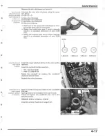
Page 463: ...T INSTALLATION 13 21 CRANKSHAFT REMOVAL 13 14 CYLINDER COMPRESSION TEST 9 7 CYLINDER HEAD ASSEMBLY 9 33 CYLINDER HEAD COVER INSTALLATlON 9 42 23 INDEX CYLINDER HEAD COVER REMOVAL 9 7 CYLINDER HEAD DiSASSEMBLy 9 27 CYLINDER HEAD INSPECTION 9 2S CYLINDER HEAD INSTALLATION 9 36 CYLINDER HEAD REMOVAL 9 24 CYLINDER HEADN ALVES SPECIFICATIONS 1 S CYLINDER INSTALLATION 10 10 CYLINDER REMOVAL 10 5 CYUNDER...

Page 464: ...ER MOTOR 19 6 STARTER RELAY SWITCH 19 13 STARTER SWiTCH 20 9 STATOR 12 5 23 2 STEERING HEAD BEARINGS 4 37 STEERING STEM 14 47 SUB FRAME 3 6 SUSPENSION 4 34 SWINGARM 15 36 SWINGARM SHOCK lINKAGE 4 35 SYSTEM DIAGRAM BATIERY CHARGING SySTEM 17 2 ELECTRIC STARTER 19 2 IGNITION SYSTEM 18 2 SYSTEM FLOW PATTERN 7 2 SYSTEM TESTING 7 5 TAILLIGHT 20 6 THROITLE OPERATION 4 9 THROTTLE POSITION SENSOR INSPECTI...

Reviews: