background image

Summary of Contents for CM400E 1981

Page 1: ......

Page 2: ...V II 1 11 tll lll I Iii j f Ii If instructions are not followed CAUTION Indicates a possibility of 11 1 1 1111 III III e lli lliiOll ilWt instructions are not fotlowcd NOTE Gives helpful infounatlou This manual should be l 0I1Nilh l d II 1 1 11 III 1 1 1 III I ill lill 11I11I1t1 should remain with the velurle WIl 11 1I ltI HONDACM400E OWNER S MANUAL _ 1981 All information in this publication is ba...

Page 3: ... THE MOTORCYCLE Also for your own and your Honda s sake please read all the written material which came with your new Honda These items include Honda Owner s Identification Card Set up and Predelivery Checklist Honda Motorcycle Emission Control System Distributor s Warranty Honda Motorcycle Distributor s Limited Warranty When service is required remember that your Honda dealer knows what it takes ...

Page 4: ...ction page 27 before you start the engine You may prevent an accident or equip ment damage 2 Many accidents involve inexperienced riders Most states require a special motorcycle riding test or license Make sure you are qualified before you ride NEVER lend your motorcycle to an inexperienced rider 3 Many automobile motorcycle acci dents happen because the automobile driver does not see the motorcyc...

Page 5: ... all motorcycle condition poor road or weather conditions etc These general guidelines may help you decide wheth er or how to equip your motorcycle and how to load it safely Loading The combined weight of the rider pas senger cargo and all accessories must not exceed 420 Ibs the vehicle capacity load Cargo weight alone should not exceed 401bs I Keep cargo and accessory weight low and close to the ...

Page 6: ...ergency 4 Do not add electrical equipment that will exceed the motorcycle s electrical system capacity A blown fuse could cause a dangerous loss of lights or engine power at night or in traffic 5 This motorcycle was not designed to pull a sidecar or trailer Handling may be seriously impaired if so equipped TIRES Proper air pressure will provide maximum stability riding comfort and tire life Check ...

Page 7: ...n those listed on the tire information label may adversely affect handling Proper wheel balance is necessary for safe stable handling of the motor cycle Do not remove or change any wheel balance weights When wheel balancing is required see your author ized Honda dealer 6 Replace tires before tread depth at the center of the tires reaches the follow ing limit Minimum tread depth Front Rear 1 5 mm 1...

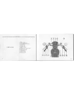
Page 8: ...urn signal switch 3 Headlight dimmer switch 4 Clutch lever 5 Choke knob 6 Speedometer 7 Ignition switch 8 Indicator and warning lights 9 Engine stop switch 10 Front brake lever 11 Throttle grip 12 Starter button 13 Fuel cap cover 8 9 ...

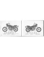
Page 9: ...latch 2 Helmet holder 1 Steering Lock 2 Fuel valve 3 Gearshift pedal 4 Foot peg 5 Side stand 7 Seat latch 6 Passenger foot peg 3 Passenger foot peg 4 Foot peg 5 Rear brake pedal 6 Oil filler cap dipstick 10 11 ...

Page 10: ...for your refer ence FRAME NO 3 H t J 0 II SlY If J 3 9 ENGINE NO i 4 00 1 YIN number 12 The VIN Vehicle Indentification Number 1 is on the Safety Certification Label affixed to the left side of the steering head This number is the same as the frame number 2 stamped on the right side of the steering head 2 Frame number The engine number 3 is stamped on the top of the crankcase 3 Engine number 13 ...

Page 11: ...o meters l Speedometer 2 Gear range indicators 3 Odometer 4 Tripmeter 5 Tripmeter reset knob 6 Turn signal indicator 7 High beam indicator 8 Oil pressure warning light 9 Neutral indicator 14 Ref No Description Function I Speedometer Shows driving speed 0 to 85 mph 2 Gear range indicators Show speed range for each gear 3 Odometer Shows accumulated mileage 4 Tripmeter Shows mileage per trip 5 Tripme...

Page 12: ...arm CAUTION Running the engine with insufficient oil pressure will cause serious engine damage 9 Neutral indicator Lights when transmission is in neutral green 16 Ignition Switch The ignition switch 1 is above the head light next to the speedometer I Ignition switch Key Position Function Key Removal OFF Engine and lights cannot be operated Remove the key Headlight taillight and meter lights will b...

Page 13: ...er Button The starter button I is below the engine stop switch 2 When the starter button is pressed the starter motor will crank the engine and the headlight will automatically go out bu t the tailligh t will stay on See pages 28 30 for the starting proce dure 1 Starter button 2 Engine stop switch The three controls next to the left han dlebar grip are Headlight Dimmer Switch l Select HI for high ...

Page 14: ...Do not operate the motorcycle with a helmet attached to the holder The helmet may interfere with the rear wheel possibly stopping the wheel J Helmet holder 2 Ignition key 3 Holder pin Seat Removal The seat is secured by a latch I on each side of the seat at the rear Pull both latches to remove the seat When re placing the seat push down firmly lift the seat to make sure the latches are secure The ...

Page 15: ...carburetors Turn the valve off whenever the motorcycle is not in use ON At ON fuel will flow from the main fuel supply to the carburetors RES At RES fuel will flow from the reserve fuel supply to the carburetors Use the reserve fuel only when the main supply is gone Refill the tank as soon as possible after switching to RES The reserve fuel supply is 3 SQ 0 9 US gal tp j j IIUCJ I Know how to oper...

Page 16: ... Do not overfill the tank there should be no fuel in the filler neck After refueling make sure the fuel cap and cover are closed securely ENGINE OIL Engine Oil Level Check Check engine oil level each day before operating the motorcycle Oil level must be maintained between the upper 1 and lower 2 oil level marks on the dipstick 3 1 Run the engine and let it idle for a few minutes Make sure the red ...

Page 17: ... is not per formed serious damage or an accident may result Inspect your motorcycle every day before you start the engine The items listed here will only take a few minutes and in the long run they can save time expense and possibly your life 1 Engine oil level add engine oil if required pages 25 26 Check for leaks 2 Fuel level fill fuel tank when neces sary page 24 Check for leaks 3 Front and rea...

Page 18: ...n 28 Starting Procedure To restart a warm engine follow the procedure for High Air Temperature 1 Choke knob A Fully Closed B Detent Position C Fully Open Normal Air Temperature IOo 3SoC SOo 9SoF I Pull the choke knob I up all the way to Fully Closed A 2 Start the engine leaving the throttle dosed CAUTION The red oil pressure warning light should go off a few seconds after the engine starts If the ...

Page 19: ... Open C Open the throttle fully and crank the engine for 5 seconds with the electric starter Turn the engine stop switch ON and follow the High Air Temperature Starting Procedure BREAK IN During the first 600 miles 1 000 km do not operate the motorcycle at more than 80 of the maximum speed in any gear Avoid full throttle operation and do not operate for a long time at one speed During initial brea...

Page 20: ...d shift down to Ist gear for acceleration fl 1 f hi iiHd Do not downshift when traveling at a speed that would force the engine to overrev in the next lower gear or cause the rear wheel to lose traction CAUTION Do not shift gears without disengaging the clutch and closing the throttle The engine and drive train could be damaged by overspeed and shock Do not tow the motorcycle or coast for long dis...

Page 21: ...rheat the brakes and reduce their effectiveness r 1 PARKING I After stopping the motorcycle shift the transmission into neutral turn the fuel valve OFF and turn the ignition switch OFF 2 Use the side stand to support the motorcycle while parked CAUTION Park the motorcycle on firm level ground to prevent overturning 3 Lock the steering to help preven t theft page 20 NOTE When stopping for a short t...

Page 22: ... verify proper assembly rMj i I iiUd Stop the engine and support the motorcycle securely on a level surface before performing these procedures 36 Tool Kit The tool kit I is in the compartment under the seat Some roadside repairs minor adjustments and parts replacement can be performed with the tools con tained in the kit Hook spanner lOX 12mm open end wrench 14 X 17mm open end wrench Pliers No 2 s...

Page 23: ...and the left fork leg When tightening the axle nut keep the handlebar and the wheel straight ahead Be sure to set the speedometer gearbox so there are no sharp bends in the speedometer cable Torque link bolt torque I B 2 5 kg m 03 1B ft lb Axle nut torque 5 0 B 0 kg m 36 58 ft Ib Install the axle holder B with the arrow 0 forward and tighten the forward holder nut 7 to the specified torque first t...

Page 24: ...rear sprocket Tilt the motorcycle to one side so that the wheel can be removed 40 1 Adjusting nut 2 Brake rod 3 Brake arm 4 Stopper arm 5 Brake panel 6 Stopper arm nut 7 Cotter pin 8 Axle nut Installation Notes To install the rear wheel reverse the removal procedure Axle nut torque 7 0 10 0 kg m 51 72 ft lb Stopper arm nut torque 1 8 2 5 kg rn 13 18 ft lb Adjust the brake page 59 and drive chain p...

Page 25: ...cover Pull the old fuse out of the clips or slide it lengthwise until one end comes out then lift it out with your fingers Push a new fuse into the clips and install the fuse box cover J N iJ Ii tij Never use a fuse with a different rating from that specified Serious damage to the electrical system or a fire may re sult causing a dangerous loss of lights or engine power at night or in traffic Do n...

Page 26: ...s designed purpose Sustained high speed operation or operation in unusually wet or dusty conditions will require more frequent service than specified in the MAINTENANCE SCHEDULE Consult your authorized Honda dealer for recom mendations applicable to your individual needs and use 44 fitV jl IIUtt If your motorcycle is overturned or involved in a collision inspect control levers cables accessories a...

Page 27: ...Page 52 WHICHEVER IODOMETER READING NOTE 3 COMES Sitff FIRST if if if iff ii ITEM s v f e EVERY 0 J Reter to DRIVE CHAIN L L EVERY Pages 61 63 300 mi 500 km BATTERY MONTH I I I I l I Pages 65 66 BRAKE SHOE WEAR I I I I I Pages 58 60 BRAKE SYSTEM I I I I I I Pages 57 60 BRAKE LIGHT SWITCH t I I I I I at HEADLIGHT AIM I I I I I I CLUTCH I I I I I I Pages 55 56 0 SIDE STAND I I I I I Page 64 SUSPENSI...

Page 28: ...t to assure complete and rapid draining I Remove the oil filler cap from the right crankcase cover 2 Place an oil drain pan under the crankcase and remove the oil drain plug l 3 Remove the oil filter bolt 2 and the cover 3 4 After the oil is completely drained make sure the sealing washer 4 on the drain plug is in good condition 5 Install the drain plug Drain plug torque 2 5 3 5 kg m 18 25 ft lb 6...

Page 29: ...cle on its side stand 2 Adjust idle speed with the throttle stop screw I Idle Speed 1 200 100 rpm I Throttle stop screw A Increase rpm B Decrease rpm Air Cleaner 1he air cleaner should be serviced at regular intervals page 46 Service more Irequently when riding in dusty areas I Remove the seat page 21 Remove the air cleaner cover screws I and the cover 2 Remove the element 3 I Screws 2 Air cleaner...

Page 30: ...r if the clutch slips causing acceleration to lag behind engine speed Normal clutch lever free play should be 10 20 mm 3 8 3 4 in at the lever 1 Minor adjustments can be made with the dutch cable adjuster 2 at the lever 10 20mm 3 8 3 4in 1 lt I Clutch lever I Pull back the ru bber dust cover 3 Loosen the lock nut 4 and turn the adjuster 2 Tighten the lock nut 4 and check adjustment 2 If the adjust...

Page 31: ...crease free play lront Brake Adjustment Measure the distance the front brake lever I moves before the brake starts to take hold The lever free play should be If 30 mm 3 4 1 1 4 in at the tip of the luuke lever I Minor adjustments can be made with the cable adjuster on the front brake lever Pull back the rubber dust cover 2 Loosen the lock nut 3 and turn the front brake cable adjuster 4 to obtain t...

Page 32: ...rk 3 on the brake panel 4 If the arrow aligns with the reference mark on full application of the brake the brake shoes must be replaced I Arrow 2 Brake arm 3 Reference mark 4 Brake panel Rear Brake Adjustment I Measure the distance the rear brake pedal I moves before the brake starts to take hold Free play should be 20 30 mm 3 4 1 1 4 in If adjustment is neces sary turn the rear brake adjusting nu...

Page 33: ... as part of the Pre ride Inspec 111111 page 27 Under severe usage or when the motorcycle is ridden in unusual ly dusty areas more frequent mainten nice will be necessary lnspection I Turn the engine off place the motor cycle on its side stand and shift the transmission into neutral I Check slack in the lower drive chain run midway between the sprockets Drive chain slack should be adjusted to allow...

Page 34: ... on both sides of the swingarm NOTE If drive chain slack is excessive when the rear axle is moved to the furthest limit of adjustment the drive chain is worn and must be replaced Tighten the rear axle nut and secure the nut with a new cotter pin Rear axle nut torque 7 0 10 0 kg rn 51 72 ft lb Tighten the lock nuts Check drive chain slack I Rear brake pedal free play is affected when repositioning ...

Page 35: ...e battery I is behind the right side rover Remove the side cover Remove the terminal leads 2 from the battery I Remove the bolt Pull out the battery 11110 check the electrolyte lhe electrolyte level must be maintained hctween the upper 3 and lower 4 level marks on the side of the battery If the olcctrolyte level is low remove the bat tl ry filler caps 5 Carefully add distilled water to the upper l...

Page 36: ...h pressure water typical in coin operated car washes at the following area Wheel Hubs Ignition Switch Muffler Outlets Steering Lock Under Fuel Tank Drive Chain Under Seat Handlebar Switches Carburetors Instruments After cleaning rinse the motorcycle thoroughly with plenty of clean water Strong detergent residue can corrode alloy parts Dry the motorcycle start the engine and let it run for several ...

Page 37: ... to form photochemical smog when subjected to sunlight Carbon monoxide does not react in the same way but it is toxic Honda Motor Co Ltd utilizes lean carburetor settings and other systems to reduce carbon monoxide and hydrocarbons Exhaust Emission Control System The exhaust emission control system is composed of lean carburetor settings and no adjustments should be made except idle speed adjustme...

Page 38: ...ON 1 VEHICLE STOPPING DISTANCE This figure indicates braking performance that can be met or exceeded by the vehicles to which it applies without locking the wheels under different con ditions of loading The information presented represents results obtainable by skilled drivers under controlled road and vehicle conditions and the information may not be correct under other conditions Description of ...

Page 39: ...z I I I 72 NGINE Bore and stroke Compression ratio Displacement Spark plugs Spark plug gap Valve clearance Idle speed 70 5 x 50 6 mm 2 78 x 1 99 in 9 3 I 395 cc 24 1 cu in USA model X24ES U ND DSEA NGK Standard For cold climate I X22ES U ND Below SoC 41 F D7EA NGK Canadian model X24ESR U ND DRSES L NGK X22ESR U ND DR7ES INGK For extended I X27ES U ND high speed driving D9EA NGK 0 6 0 7 mm 0 024 0 ...

Page 40: ...AE NO 1 034 3rd 1 417 1 Rear turn signal 32 cp 23 W SAE NO 1 073 4th 1 148 I Meter lights 2 cp 3 4 W SAE NO 57 5th 0 966 I Neutral indicator 2 cp 3 4 W SAE NO 57 Tum signal indicator 2cp 3 4W SAE NO 57 ELECTRICAL lligh beam indicator 2 cp 3 4 W SAE NO 57 I Battery 12 V 12 AH Oil pressure warning 2 cp 3 4 W SAE NO 57 Generator A C Generator 0 17 kw 5 000 rpm indicator I I I USE 15 A for main 7 A fo...

Page 41: ......

Page 42: ......

Page 43: ...lully 111 1I vh Manager contact the owner of the dealership or inc GCIllIIIII MIII I 1 If your problem still has not been resolved to your SIlII llIlllllli 111111 1 I Iii Customer Service Department AMERICAN JlON OA MO J iu I ll INI III I Boulevard Gardena California 90247 213 327 8280 11111 IlIllvldl 1111111 Iill your name address and telephone number Vehicle frame number Dealer s name and locati...

Reviews: