3.
REMOVAL AND INSTALLATION
3-1. PREPARATION AND PRECAUTIONS
1) For safety, drain engine oil and gasoline to before work.
2) Be sure to memorize the location of individual parts when disassembling the generator so
that the generator can be reassembled correctly.
Tag the disassembled part with the necessary information to facilitate easier and smoother
reassemble.
3) For more convenience, divide the parts into several groups and store them in boxes.
4) To prevent bolts and nuts from being misplaced or installed incorrectly, replace them
temporarily to their original position.
5) Handle disassembled parts with care; clean them before reassemble using a neutral cleaning
fluid.
6) Use all disassembly / assembly tools properly, and use the proper tool for each specific job.
TORQUE VALUES
Item
Thread Dia.
(mm)
Torque Values
(N・m)
Remark
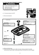
Fuel valve mount nut
-
20.0
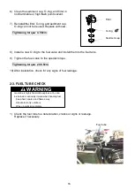
Sediment cup
-
4.5
Generator rotor bolt
M10 , P1.25
45.0
Exhaust pipe mount nut
M8 , P1.25
22.0
Exhaust pipe mount bolt
M8 , P1.25
22.0
brush holder mount bolt
M5
3.0
AVR unit mount bolt
M5
3.0
STANDARD TORQUE VALUES
Item
Thread Dia.
(mm)
Torque Values
(N
・
m)
Remark
Screw
M4
1.4
Bolt and nut
M5
4.0
M6
7.0
M8
15.0
M10
27.0
Regarding Engine torque values, please refer and confirm HONDA ENGINE shop manual.
17
Summary of Contents for EZ6500CXS
Page 1: ......
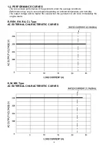
Page 10: ...L LB Type AC EXTERNAL CHARACTERISTIC CURVES S SB Type AC EXTERNAL CHARACTERISTIC CURVES 10 ...
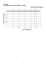
Page 11: ...LS Type AC EXTERNAL CHARACTERISTIC CURVES 11 ...
Page 44: ...4 4 ALTERNATING CURRENT VOLTAGE IS OV 44 ...
Page 51: ...4 11 WIRING DIAGRAM R S K Type 51 ...
Page 52: ...RK LS MK Type 52 ...
Page 53: ...REH CL Type 53 ...
Page 54: ...M Type 54 ...
Page 55: ...SB LB Type 55 ...
Page 56: ...L Type 56 ...
Page 57: ...62EAB00 2019 Sep ...

